
The Fuel and Engine Bible - how engines work including 2 stroke, 4 stroke and wankel (rotary) engines, fuel, octane rating, power, bhp, gas types and grades, carburettors, fuel injection, tuning, tweaking, nitrous, turbos, superchargers, chipping, hybrids, how to keep your engine running at peak fitness and much more.
The Fuel & Engine Bible
Spark plugs
And engine without a spark plug is useless, unless it's a diesel engine in which case it uses a glowplug instead. But we're talking about regular petrol engines here so the next topic to get to grips with is the spark plug. It does exactly what it says on the tin - it's a plug that generates a spark. Duh. So why spend time talking about it? Well with apologies to George Orwell not all spark plugs are created equal. Some are more equal than others. They'll all do the job but the more you pay, the better the plug. All spark plugs share the same basic design and construction though.
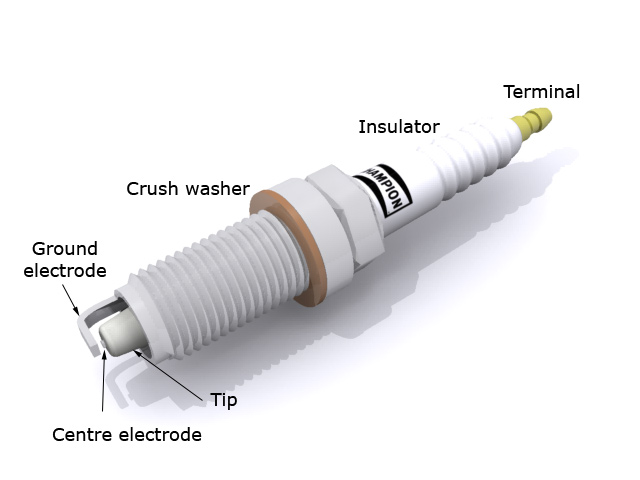
The high voltage from your vehicle's high-tension electrical system is fed into the terminal at the top of the spark plug. It travels down through the core of the plug (normally via some noise-suppression components to prevent electrical noise) and arrives at the centre electrode at the bottom where it jumps to the ground electrode creating a spark. The crush washer is designed to be crushed by tightening the spark plug down when it's screwed into the cylinder head, and as such, it helps keep the screw threads under tension to stop the spark plug from shaking loose or backing out. The insulator basically keeps the high-tension charge away from the cylinder head so that the spark plug doesn't ground before it gets a chance to generate the spark.
The type of plug I've illustrated here is known as a projected nose type plug, because the tip extends below the bottom of the spark plug itself. The other main type of spark plug has the centre electrode recessed into the plug itself and merely grounds to the collar at the bottom. The advantage of the projected nose type is that the spark is better exposed to the fuel-air mixture.
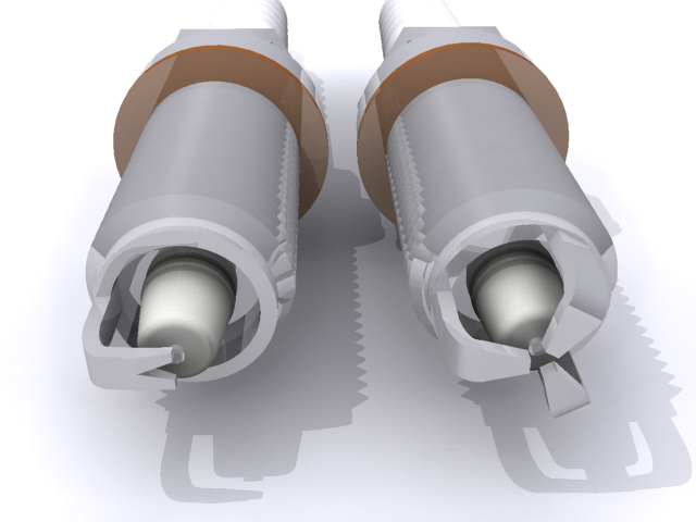
Ground electrode (ground strap) types.There are plenty of different types of grounding electrodes kicking around in spark plug designs nowadays, from 'Y' shaped electrodes (like SplitFire plugs) to grooved electrodes like you'll find on Champion plugs all the way up to triple-electrode plugs like the high-end Bosch items. They're all designed to try to get a better spark, and to that end, you'll now find all sorts of exotic materials turning up too. Titanium plugs, for example, have better electrical conductivity than brass and steel plugs, and the theory is that they'll generate a stronger, more reliable spark.
Gapping a spark plug. Gapping a spark plug is the process of ensuring the gap between the two electrodes is correct for the type of engine the plug is going to be used in. Too large a gap and the spark will be weak. Too small and the spark might jump across the gap too early. Generally speaking, the factory-set spark plug gap is just fine, but if you're running an older engine, or a highly tuned engine, then you need to pay attention to the gap. Feeler gauges are used to measure the gap, and a gapping tool is used to bend the outer electrode so that the gap is correct.
Heat ranges. Something that is often overlooked in spark plugs is their heat rating or heat range. The term "heat range" refers to the relative temperature of the tip of the spark plug when its working. The hot and cold classifications often cause confusion because a 'hot' spark plug is normally used in a 'cold' (low horsepower) engine and vice versa. The term actually refers to the thermal characteristics of the plug itself, specifically its ability to dissipate heat into the cooling system. A cold plug can get rid of heat very quickly and should be used in engines that run hot and lean. A hot plug takes longer to cool down and should be used in lower compression engines where heat needs to be retained to prevent combustion byproduct buildup.
Like the site? The page you're reading is free, but if you like what you see and feel you've learned something, a small donation to help pay down my car loan would be appreciated. Thank you.
How does the fuel-air mix happen? Magic?
You keep seeing me talk about fuel-air mix or fuel-air charge on this page, but I thought it wise to explain how this happens because it is pretty fundamental to the operation of internal combustion engines.
The fuel and air are mixed in one of two main ways. The old-school method is to use a carburetor, whilst the new-tech approach is to use fuel injectors. The basic purpose is the same though, and that is to mix the fuel and air together in proportions that keep the engine running. Too little fuel and the engine runs 'lean' which makes it run hot. Too much fuel and it runs 'rich' which conversely makes the engine run cooler. Running rich can also result in fouled up spark plugs, flooded engines and stalling, not to mention wasting fuel. Finding the right balance normally involves about 10 milligrams of petrol for each combustion stroke.
Carburetors
Advantages : analogue and very predictable fuelling behaviour, simple and inexpensive to build and maintain.
Disadvantages : carburetor icing in the venturi, imprecise fuel metering, float chambers don't work well if they're not the right way up.
How they work.
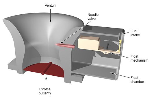
A carburetor is basically a shaped tube. The shape of the tube is designed to swirl the incoming air and generate a vacuum in a section called the venturi pipe (or just the venturi). In the side of the venturi is a fuel jet which is basically a tiny hole connected to the float chamber via a pipe. It's normally made of brass and has a miniscule hole in the end of it which determines the flow of fuel through it. In more complex carburetors, this is an adjustable needle valve where a screw on the outside of the carburetor can screw a needle in and out of the valve to give some tuning control over the fuel flow. The fuel is pulled through the jet by the vacuum created in the venturi. At the bottom of the tube is a throttle plate or throttle butterfly which is basically a flat circular plate that pivots along its centreline. It is connected mechanically to the accelerator pedal or twist-grip throttle via the throttle cable. The more you push on the accelerator or twist open the throttle, the more the throttle butterfly opens. This allows more air in which creates more vacuum, which draws more fuel through the fuel jet and gives a larger fuel-air charge to the cylinder, resulting in acceleration.
When the throttle is closed, the throttle butterfly in the carburetor is also closed. This means the engine is trying to suck fuel-air mix and generating a vacuum behind the butterfly valve so the regular fuel jet won't work. To allow the engine to idle without shutting off completely, a second fuel jet known as the idle valve is screwed into the venturi downwind of the throttle butterfly. This allows just enough fuel to get into the cylinders to keep the engine ticking over.
Float and diaphragm chambers.
To make sure a carburetor has a good, constant supply of fuel to be sucked through the fuel jets, it has a float chamber or float bowl. This is a reservoir of petrol that is constantly topped up from the fuel tank. Petrol goes through an inline filter and a strainer to make sure it's clean of contaminants and is then deposited into the float chamber. A sealed plastic box is pivotted at one end and floats on top of the fuel. Believe it or not, this is called the float. A simple lever connects to the float and controls a valve on the fuel intake line. As the fuel drops in the float chamber, the float drops with it which opens the valve and allows more fuel in. As the level goes up, the float goes up and the valve is restricted. This means that the level in the float chamber is kept constant no matter how much fuel the carburetor is demanding through the fuel jets. The quicker the level tries to drop, the more the intake valve is opened and the more petrol comes in to keep the fuel level up. This is why carburetors don't work too well when they're tipped over - the float chamber leaks or empties out resulting in a fuel spill - something you don't get with injectors. To combat this, another type of chamber is used where carburetors can't be guaranteed to be upright (like in chainsaws). These use diaphragm chambers instead. The principle is more or less the same though. The chamber is full of fuel and has a rubber diaphragm across the top of it with the other side exposed to ambient air pressure. As the fuel level drops in the chamber, the outside air pressure forces the diaphragm down. Because it's connected to an intake valve in the same way that the float is in a float chamber, as the diaphragm is sucked inwards, it opens the intake valve and more fuel is let in to replenish the chamber. Diaphragm chambers are normally spill-proof.
Carb icing.
One of the problems with the spinning, compressing, vacuum-generating properties of the venturi is that it cools the air in the process. Whilst this is good for the engine (colder air is denser and burns better in a fuel-air mix), in humid environments, especially cool, humid environments, it can result in carburetor icing. When this happens, water vapour in the air freezes as it cools and sticks to the inside of the venturi. This can result in the opening becoming restricted or cut off completely. When carbs ice up, engines stop. In aircraft engines, there is a control in the cockpit called "carb heat" which either uses electrical heating elements to heat up the venturi to prevent icing, or reroutes hot air from around the exhausts back into the carburetor intakes. In cars, we don't have "carb heat" but instead there's normally a heat shield over the exhaust manifold connected via a pipe to a temperature-controlled valve at the air filter. When its cold, the valve is open and the air filter draws warm air from over the exhaust manifold and feeds it into the carburetor. As the temperature warms up, the valve closes and the carburetor gets cooler air because the risk of icing has reduced. The symptoms of carb icing are pretty easy to diagnose. First, your engine bogs down at high throttle then it loses power and ultimately could stall completely. You'll stop on the side of the road and wait a couple of minutes, then the engine will start and run normally. This is because with the engine off, the heat from the engine starts to warm up the carbs and melts the ice so that when you try to start it up again, everything is fine.
Complexity for the sake of it.
As car engines evolved, carburetors had to evolve to cope with the various demands. It's not unusual to find five-circuit carburetors which have become so complex that they're a nightmare to design, build and maintain. That flies in the face of one of the carburetor's advantages, which used to be that they were simple. Why five circuits? The main circuit is the one which provides day-to-day running capability. It's augmented by accelerator and load (or enrichment) circuits which can vary the fuelling to accomodate sudden acceleration or the need for more power (like driving uphill). The accelerator circuit also adds a second butterfly valve in most cases which only opens at 70% throttle or more. Then there's the choke circuit designed to provide extra fuel with the throttles closed when the engine is cold, allowing it to start, and finally the idle circuit which does the same thing but when the engine is warm, to keep it going. On top of all of this, with the introduction of stricter emissions requirements came catalytic converters, and these expensive boxes of rare metals just don't work well unless the fuel-air ratio is very carefully controlled. And that's something carburetors just couldn't keep up with. Small wonder then that this mechanical tomfoolery gave way to fuel injection......
Fuel injection
Advantages : precise and variable fuel metering, better fuel efficiency and better emissions.
Disadvantages : Fairly complex engineering that isn't very user-friendly. Binary on/off functionality at low throttles, which is especially noticable on motorbikes where the throttle becomes 'snatchy' and it becomes hard to ride smoothly at low speed.
How it works.
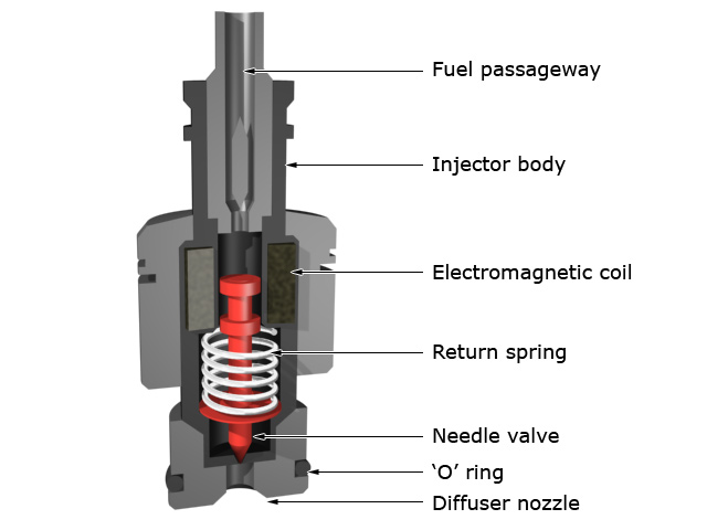
Compared to carburettors, fuel injectors themselves are incredibly simple. They are basically electro-mechanically operated needle valves. The image on the right shows a cutaway of a representative fuel injector. When a current is passed through the injector electromagnetic coil, the valve opens and the fuel pressure forces petrol through the spray tip and out of the diffuser nozzle, atomising it as it does so. When current is removed, the combination of a spring and fuel back-pressure causes the needle valve to close. This gives an audible 'tick' noise when it happens, which is why even a quiet fuel-injected engine has a soft but rapid tick-tick-tick-tick noise as the injectors fire. This on-off cycle time is known as the pulse width and varying the pulse width determines how much fuel can flow through the injectors. When you ask for more throttle either via the accelerator pedal or twist-grip (on a motorbike) you're opening a butterfly valve similar to the one in a carburettor. This lets more air into the intake system and the position of the throttle is measured with a potentiometer. The engine control unit (ECU) gets a reading from this potentiometer and "sees" that you've opened the throttle. In response the ECU increases the injector pulse width to allow more fuel to be sprayed by the injectors. Downwind of the throttle body is a mass airflow sensor. This is normally a heated wire. The more air that flows past it, the quicker it disappates heat and the more current it needs to remain warm. The ECU can continually measure this current to determine if the fuel-air mix is correct and it can adjust the fuel flow through the injectors accordingly. On top of this, the ECU also looks at data coming from the oxygen (lambda) sensors in the exhaust. These tell the ECU how much oxygen is in the exhaust so it can automatically adjust for rich- or lean-running.
Different types of injector systems.
When fuel-injection was first introduced, it was fairly simple and used a single injector in the throttle body. Basically it was a carburettor-derivative but instead of having the induction vacuum suck fuel into the venturi, an injector forced fuel into the airflow. This was known as throttle-body fuel-injection, or single-point fuel-injection.
As engine design advanced, the single-point system was phased out and replaced with multi-point or multi-port fuel-injection. In this design, there is one injector for each cylinder, normally screwed into the intake manifold and aimed right at the intake valve. Because fuel is only sprayed when the intake valve is open, this systems provides more accurate fuel-metering and a quicker throttle response. Typically, multi-point injection systems have one more injector for cold-starting which sprays extra fuel into the intake manifold upstream of the regular injectors, to provide a richer fuel-air mix for cold starting. A coolant temperature sensor feeds information back to the ECU to determine when this extra injector should be used.
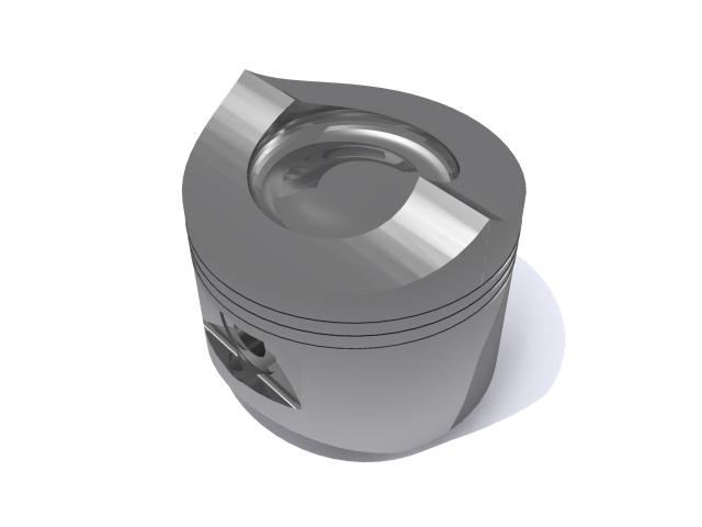
As you would expect though, technology marches on with no regard to home mechanics, and the latest technology is direct injection, also known as GDI (gasoline direct injection). This is similar to multi-point injection only the injectors are moved into the combustion chambers themselves rather than the intake manifold. This is nearly identical to the direct injection system used in diesel engines. Essentially, the intake valve only allows air into the combustion chamber and the fuel is sprayed in directly through a high-pressure, heat-resistant injector. The fuel and air mix inside the combustion chamber itself due to the positions of the intake valve, injector tip and top of the piston crown. The piston crown in these engines is normally designed to create a swirling vortex to help mix the fuel and air before combustion, as well as having a cavity in it for ultra-lean-burn conditions (see picture to the left). The ECU controls the amount of fuel injected based on the airflow into the engine and demand, and will operate a direct injection engine in one of three modes: Full power mode is basically foot-to-the-floor driving. The fuel-air ratio is made richer and the injectors spray the fuel in during the piston intake stroke. In stoichiometric mode the fuel-air ratio is leaned off a little. The fuel is still sprayed in during the piston intake stroke but the burn is a lot cleaner and the ECU chooses this mode when the load on the engine is slightly higher than normal, for example during acceleration from a stop. Finally, when you're cruising with very little engine load, for example when you're on wide-open motorway with no traffic (I know that's hard to imagine when you live in England), the ECU will choose an ultra lean mode. In this mode, the fuel is injected later on in the 4 stroke cycle - as the piston is moving up its compression stroke. This forces the fuel-air charge right up next to the tip of the spark plug for the best burn conditions and the combustion itself takes place partly in the cylinder and partly in the shaped piston crown mentioned previously.
ECU maps.
The ECU receives a wide number of sensor readings from all over the engine. Built into the ECU is a fuelling and ignition map which is basically a gigantic table of numbers. It's like a lookup table that the ECU uses to determine injector pulse width, spark timing (and on some engines, the variable valve timing). So the ECU receives a set of values from all its sensors, which it then looks up in the fuelling and ignition map. At the point where all these numbers coincide, there is final number which the ECU then uses to set the injector pulse width. These are the manufacturer's "blessed" fuelling routines, and elsewhere on this page, there's a section dealing with chipping and remapping, whereby aftermarket tuners can alter these mapping tables to make the engine behave differently.
Valves and valve mechanisms
If you've got this far down the page, hopefully you understand that the valves are what let the fuel-air mixture into the cylinder, and let the exhaust out. Seems simple enough, but there are some interesting differences in the various types of valve mechanism.
Spring-return valves.
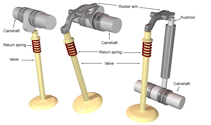
Spring return valves are about the most commonly-used and most basic type of valvetrain in engines today. Their operation is simplicity itself and there are only really three variations of the same style. The basic premise here is that the spinning camshaft operates the valves by pushing them open, and valve return springs force them closed. The cam lobes either operate directly on the top of the valve itself, or in some cases, on a rocker arm which pivots and pushes on the top of the valve. The three variations of this type of valve-train are based on the combination of rocker arms (or not) and the position of the camshaft.
The most basic type has the camshaft at the top of the engine with the cam lobes operating directly on the tops of the valves.
The second more complex type still has the camshaft at the top of the engine, but the cam lobes operate rocker arms, which in turn pivot and operate on the tops of the valves. With some of these designs, the rocker arm is pivoted in the middle (as shown here) and with other designed, it's pivoted at one end and the cam lobe operates on it at the midpoint. Think of a fat bloke bouncing in the middle of a diving board whilst the tip of the board hits a swimmer on the head and you'll get the general idea.
The third type which you'll find in some motorcycle engines and many boxer engines are pushrod-activated valves. The camshaft is actually directly geared off the crank at the bottom of the engine and the cam lobes push on pushrods which run up the sides of the engine. The top of the pushrod then pushes on a rocker arm, which finally pivots and operates on the top of the valve. The image here shows the three derivatives in their most basic form so you can see the differences between them. Note that the pushrod type shows the camshaft in the wrong place simply for the purpose of getting it into the image. In reality the camshaft in this system is right at the bottom of the engine near the crank. The rocker arms shown here are also called fingers, or followers depending on who you talk to.
Tappet Valves
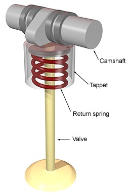
Tappet valves aren't really a unique type of valve but a derivative of spring-return valves. For the most part, the direct spring return valve described above wouldn't act directly on the top of the valve itself, but rather on an oil-filled tappet. The tappet is basically an upside-down bucket that covers the top of the valve stem and contains the spring. It's normally filled with oil through a small hole when the engine is pressurised. The purpose of tappets is two-fold. The oil in them helps quiet down the valvetrain noise, and the top of the tappet gives a more uniform surface for the cam lobe to work on. From a maintenance point of view, tappets are the items which wear and are a lot easier to swap out than entire valve assemblies. The image on the left shows a simple tappet valve assembly. I've rendered the tappet slightly transparent so you can see the return spring inside.
Desmodromic Valves
Desmodromic valve systems are unique to Ducati motorbikes. From the Ducati website: The word 'desmodromic' is derived from two Greek roots, desmos (controlled, linked) and dromos (course, track). It refers to the exclusive valve control system used in Ducati engines: both valve movements (opening and closing) are 'operated." Classy, but what does it mean. Well in both the above systems, the closure mechanism on the valve relies on mechanical springs or hydraulics. There's nothing to actually force the valve to close. With the Ducati Desmodromic system, the camshaft has two lobes per valve, and the only spring is there to take up the slack in the closing system. That's right; Ducati valves are forced closed by the camshaft. The marketing people will tell you it's one of the reasons Ducati motorbike engines have been able to rev much higher than their Japanese counterparts. The idea is that with springs especially, once you get to a certain speed, you're bound by the metallurgy of the spring - it can no longer expand to full length in the time between cylinder strokes and so you get 'valve float' where the valve never truly closes. With Desmodromic valves, that never happens because a second closing rocker arm hooks under the top of the valve stem and jams it upwards to force the valve closed. In fact, the stroke length, rods, and pistons all play their part in valve timing and maximum engine speed - it's not just the springs and valve float. This is why F1 cars use such a small stroke and pneumatic valves springs. In truth, both systems, spring or Desmodromic only work well up to a limit. Newer Japanese bikes have engines that can rev to the same limit as a Ducati just using spring-return valves.
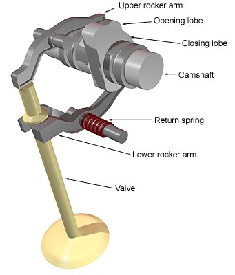
You can see the basic layout of a desmodromic valve on the right. As the cam spins, the opening lobe hits the upper rocker arm which pivots and pushes the valve down and open. As the cam continues to spin, the closing lobe hits the lower rocker arm which pivots and hooks the valve back up, closing it. The red return spring is merely there to hold the valve closed for the next cycle and doesn't provide any springing force to the closing mechanism. This is a fairly simple layout for the purposes of illustration. The real engines have Desmo-due and Desmo-quattro valve systems in them where pairs of valves are opened and closed together via the same mechanism.
Quattrovalvole, 16v and the other monikers you'll find on the back of a car.
In the 80's, the buzzword was 16-valve. If you had a 16-valve engine you were happening. You were the dogs bollocks, the cat's meouw. In Italy, your engine was a quattrovalvole. So what the heck does all this mean? Well it's really, really simple. "Traditional" 4-cylinder in-line engines have two valves per cylinder - one intake and one exhaust. In a 16V engine, you have four per cylinder - two intake and two exhaust. (4 valves) x (4 cylinders) = 16 valves, or 16V. It follows that a 20V engine has 20 valves - 5 per cylinder. Normally three intake and two exhaust. Unless you've got a 5-cylinder Audi or Volvo in which case you've still got 4 valves per cylinder. If you're in America, the thing to have now is 32V - a 32 valve engine. Basically it's a V-8 with 4 valves per cylinder. See - it's all just basic maths.
And what do all these extra valves get you apart from a lot more damage if they ever go wrong? A better breathing engine. More fuel-air mix in, quicker exhaust. When you get further down the page (and if your wife / husband hasn't come and complained to you about spending so damn long reading this stuff so late at night), you'll find some more information on why this is A Good Thing.
Variable Valve Timing
An interesting topic which is useless without illustration, so instead of bogging this page down even more, Variable Valve Timing has it's own page.
Rotary / Wankel engines
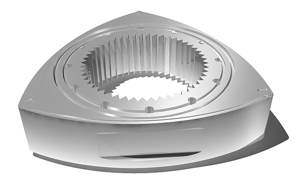
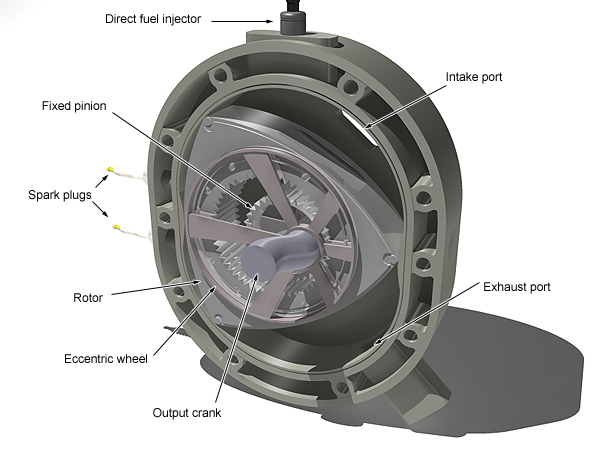
So you've got this far down the page and realised how ridiculously complicated traditional 2 stroke and 4 stroke engines are. The pistons, connecting rods and crank are all there to turn up-down motion into spinning motion. Then there's the complexity of valves and valve trains, timing belts, tappets, springs, fuel delivery systems etc.etc. There is a simpler way. Would you believe the rotary engine essentially has only three moving parts? Conceived in 1957 by Dr. Felix Wankel, the rotary engine (also known as the Wankel Engine or Wankel Motor) works on a very simple principle. The piston isn't a piston at all, but a three-sided convex rotor. The rendering to the right shows a typical example. When spun around a fixed pinion gear inside an epitrochoidal-shaped chamber, the spinning of the rotor creates the suck-squeeze-bang-blow cycle simply by the its position relative to the sides of the chamber. (If you ever used a Spirograph as a kid, you'll have drawn trochoidal shapes without really knowing it). Basically, the combination of the rotor and chamber shapes ensures that the three apexes of the rotor are always in contact with the chamber walls whilst at the same time always creating three different volumes. As the rotor spins, each volume gets larger and smaller in turn, creating the compression and expansion volumes required for the engine to work. But how does the spinning rotor connect to the output shaft? There's an eccentric wheel that sits in a bearing inside the rotor. The spinning rotor transfers its motion to the eccentric wheel and the centre of that wheel is connected to a crank on the output shaft.
A single Wankel rotor could therefore be considered to be the equivalent of three pistons in a regular 4 stroke engine. The image below shows a single chamber of a typical rotary engine. Most rotary engines use two chambers and thus two rotors. Hence the three moving parts - the two rotors and the one output shaft. You can see there are no valves required - the intake and exhaust ports are simple openings in the combustion chamber that are covered and uncovered in the correct sequence by the spinning of the rotor.
At this point you're now asking yourself two questions.
The first is this - "If this is such a simple design, why doesn't everyone use it?"
Well yes, the design is simple. It's also smooth. Both rotors are continuously turning in the same direction so you don't have the violent change of direction problem that a normal engine has (up/down/up/down). As well as that, the design means that the combustion cycle lasts through three quarters of each complete turn of the rotor, as compared to one quarter of every second stroke of a 4 stroke engine. But all this clever design does have some inherent problems. Rotary engines cost more to manufacture because of the engineering tolerances required to make them work. The seals at the rotor apexes have to be very finely manufactured to prevent premature wear. (The apex seals are the equivalent of the piston rings in a normal engine). The low compression ratio and relatively large combustion volumes mean that Wankel engines are also typically less fuel efficient than normal engines, and a side-effect of that it is typically more difficult to get these engines to pass emissions regulations. It's not impossible though. Mazda saw the benefits of rotary engines back in 1961 and to-date have been the only manufacturer willing to spend the time, money and resources required to get a reliable, mass-producable design. Their current generation Renesis (Rotary Engine Genesis) engine powers the Mazda RX-8. Mazda have a plentiful supply of information on the history, design and implementation of their engines. Mazda rotary engines.
The second question is "Can I see an animation of this pinnacle of engineering prowess?". The answer is yes because it won't make much sense otherwise. The easiest way to understand how this all works it to keep your eye on just one of the curved sides of the rotor as it spins and observe the size of the volume between it and the chamber wall. As it passes in the intake port, the volume gets larger, generating a vacuum which pulls air into the chamber. As it passes the top, fuel is injected. As it approaches the left side of the chamber, the volume gets much smaller, creating the compression. At that point, the spark plugs fire. The combustion process causes the expansion of the gas which forces the rotor to continue its motion. Again thinking of just one side of the rotor, you'll see the volume increase in size again (to accomodate the combustion). Finally the leading rotor apex uncovers the exhaust port and as the volume decreases again, the exhaust gasses are forced out. At this point, that one side of the rotor is now ready to start its combustion cycle again. The bigger picture of course is that while the side you were watching was going through its intake cycle, the second side was going through its compression cycle and the third side was going through its exhaust cycle. Hence why a single-rotor wankel engine is the equivalent of a three-cylinder four-stroke engine. During that entire cycle you'll have noticed the eccentric ring spinning in its bearing and in turn spinning the output crank.
Engine Cooling Systems
It stands to reason that if you fill a metal engine with fuel and air hundreds of times a second and make it explode, the whole thing is going to get pretty hot. To stop it all from melting into a fused lump of steel and aluminium, all engines have some method of keeping them cool.
Air cooling
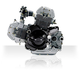
You don't see this much on car engines at all now. The most famous cars it was used on were rear-engined boxers like the original VW Beetle, Karmann Ghia, and Porsche Roadsters. It is still used a lot on motorbike engines because it's a very simple method of cooling. For air cooling to work, you need two things - fins (lots of them) and good airflow. An air-cooled engine is normally easy to spot because of the fins built into the outside of the cylinders. The idea is simple - the fins act as heat sinks, getting hot with the engine but transferring the heat to the air as the air passes through and between them. Air-cooled engines don't work particularly well in long, hot traffic jams though, because obviously there's very little air passing over the fins. They are good in the winter when the air is coldest, but that illustrates a weak spot in the whole design. Air cooled engines can't regulate the overall temperature of the cylinder heads and engine, so the temperature tends to swing up and down depending on engine load, air temperature and forward speed. A famous problem with air-cooling is associated with V-twin motorcycles. Because the rear cylinder is tucked in the frame behind the front cylinder, its supply of cool, uninterrupted air is extremely limited and so in these designs, the rear cylinder tends to run extremely hot compared to the front.
The image on the right is ©Ducati and shows the engine from the Monster 695 motorbike. It's a good example of modern air-cooled design and you can see the fins on the engine are all angled towards the direction of travel so the air can flow through them freely.
Oil cooling
To some extent, all engines have oil-cooling. It's one of the functions of the engine oil - to transfer heat away from the moving parts and back to the sump where fins on the outside of the sump can help transfer that heat out into the air. But for some engines, the oil system itself is designed to be a more efficient cooling system. BMW 'R' motorbikes are known for this (their nickname is 'oilheads'). As the oil moves around the engine, at some points it's directed through cooling passageways close to the cylinder bores to pick up heat. From there it goes to an oil radiator placed out in the airflow to disperse the heat into the air before returning into the core of the engine. Actually, in the case of the 'R' motorbikes, they're air- and oil-cooled as they have the air-cooling fins on the cylinders too. For a quick primer on how the radiator itself works, read on....
Water cooling
This is by far and away the most common method of cooling and engine down. With water cooling, a coolant mixture is pumped around pipes and passageways inside the engine separate to the oil, before passing out to a radiator. The radiator itself is made of metal, and it forces the coolant to flow through long passageways each of which have lots of metal fins attached to the outside giving a huge surface area. The coolant transfers its heat into the metal of the radiator, which in turn transfers the heat into the surround air through the fins - essentially just like the air-cooled engine fins. The coolant itself is normally a mixture of distilled water and an antifreeze component. The water needs to be distilled because if you just use tap water, all the minerals in it will deposit on the inside of the cooling system and mess it up. The antifreeze is in the mix, obviously to stop the liquid from freezing in cold weather. If it froze up, you'd have no cooling at all and the engine would overheat and weld itself together in a matter of minutes. The antifreeze mix normally also has other chemicals in it for corrosion resistance too and when mixed correctly it raises the boiling point of water, so even in the warmer months of the year, a cooling system always needs a water / antifreeze mix in it.
The coolant system in a typical car is under pressure once the engine is running, as a byproduct of the water pump and the expansion that water undergoes as it heats up. Because of the coolant mixture, the water in the cooling system can get over 100°C without boiling which is why it's never a good idea to open the radiator cap immediately after you've turned the engine off. If you do, a superheated mixture of steam and coolant will spray out and you'll spend some quality time in a burns unit.
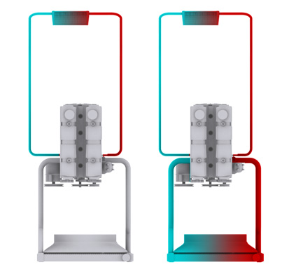
The complexities of water cooling. Water cooling is the most common method of cooling and engine down, but it's also the most complicated. For example you don't want the coolant flowing through the radiator as soon as you start the engine. If it did, the engine would take a long time to come up to operating temperature which causes issues with the emissions systems, the drivability of the engine and the comfort of the passengers. In truly cold weather, most water cooling systems are so efficient that if the coolant flowed through the radiator at startup, the engine would literally never get warm. So this is where the thermostat comes in to play. The thermostat is a small device that normally sits in the system in-line to the radiator. It is a spring-loaded valve actuated by a bimetallic spring. In layman's terms, the hotter it gets, the wider open the valve is. When you start the engine, the thermostat is cold and so it's closed. This redirects the flow of coolant back into the engine and bypasses the radiator completely but because the cabin heater radiator is on a separate circuit, the coolant is allowed to flow through it. It has a much smaller surface area and its cooling effect is nowhere near as great. This allows the engine to build up heat quite quickly. If you look at the first of the two diagrams on the right, you can see the representation of the coolant flow in a cold engine.
As the coolant heats up, the thermostat begins to open and the coolant is allowed to pass out to the radiator where it dumps heat out into the air before returning to the engine block. Once the engine is fully hot, the coolant is at operating temperature and the thermostat is permanently open, redirecting almost all the coolant flow through the radiator. If you look at the second of the two diagrams on the right, you can see the representation of the coolant flow in a hot engine.
It's the action of the thermostat that allows a water-cooled engine to better regulate the heat in the engine block. Unlike an air-cooled engine, the thermostat can dynamically alter the flow of coolant depending on engine load and air temperature to maintain an even temperature.
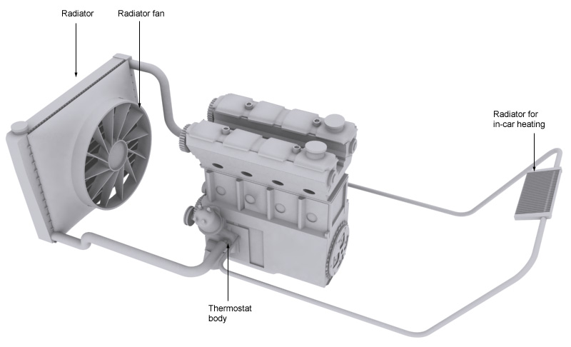
The radiator fan. In the good old days, car radiators had belt-driven fans that spun behind the radiator as fast as the engine was spinning. The fan is there to draw the warm air away from the back of the radiator to help it to work efficiently. The only problem with the old way of doing it was that the fan ran all the time the engine was running, and stopped when the engine stopped. This meant that the radiator was having air drawn through it at the same rate in freezing cold conditions as it was on a hot day, and when you parked the car, the radiator basically cooked because it had no airflow while it was cooling down. So nowadays, the radiator fan is electric and is activated by a temperature sensor in the coolant. When the temperature gets above a certain level, the fan comes on and because it's electric, this can happen even once you've stopped the engine. This is why sometimes on a hot day, you can park up, turn off, and hear the radiator fan still going. It's also the reason there are big stickers around it in the engine bay because if you park and open the hood to go and start messing with something, the fan might still come on and neatly separate you from your fingers.
The cabin heater. Most water-cooled car engines actually have a second, smaller radiator that the coolant is allowed to flow through all the time for in-car heating. It's a small heat-exchanger in the air vent system. When you select warm air with the heater controls, you will either be allowing the coolant to flow through that radiator via an inline valve in the cooling system (the old way of doing it) or moving a flap to allow the warm air already coming off that radiator to mix in with the cold air from outside.
It's all these combinations and permutations of plumbing in a water-cooled engine that make it so relatively complex.
No matter what type of cooling you choose for your car, it requires careful maintenance, which the confident do-it-yourselfer can accomplish at home. You will be dealing with some common hand tools and shop supplies, antifreeze, thermostat and gasket, caps for the radiator and other stuff. Let's be honest - when it comes to buying parts, we try to do it as quickly as possible. Fortunately, there are a lot of places online, where you can get all this without headache. One of them is CARiD.com, They carry the finest Performance Engine Cooling systems and parts the industry can offer: http://www.carid.com/performance-engine-cooling.html Except the wide choice of all needed parts for your Cooling system, you will be surprised with their attractive prices.
Overheating on a snow day
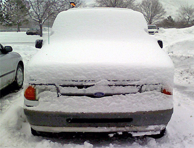
If you live anywhere where it snows a lot, you'll have seen hundreds of motorists stranded at the side of the road, hood up, with steam pouring out of their radiators on the worst weather days - when it's snowing hard. It's counterintuitive at first - surely on the coldest, snowiest day of the year, the last thing you'd need to worry about was engine cooling? Well - sort of. If you're going on a long-distance drive - hours on end on the motorway, you probably need to consider covering part of your radiator so it doesn't get too much cold air - otherwise your engine will never quite get hot. That's rare though. More common is the lazy motorist syndrome, where they'll come out to the car park, clear the snow off the driver's side of the windscreen, get in and drive. Ten minutes later, they're standing at the side of the road, freezing, in driving snow, wondering why their engine blew up. Simple. They didn't clear the snow and ice away from in front of the radiator grille on the front of their car. That large lump of snow and ice blocks the airflow to the radiator so the engine just gets hotter and hotter until eventually it overheats and blows the radiator or pressure relief valve. It's not helped by the fact that on a good snow day, you'll be stuck in 5mph traffic anyway so there's not even a chance the snow might dislodge itself. So don't be lazy - spend the extra 2 seconds to brush that stuff away from the front bumper before you get in.
Why is good engine cooling important? Case Study : the BMC Mini Minor
The importance of overall engine design and cooling system design and efficiency is very well illustrated by the fate that befell the original British Motor Corporation Mini Minor. The following contribution is by Rodney Brown - a reader of this site.
In the Morris Mini, the water pump, fan and radiator block were mounted in the same position as they were on the same 948cc engine which was concurrently being used in the more conventional fore & aft engine layout of the Morris Minor 1000 saloon. Both cars were designed by Alec Issegonis, and this was just post-war; England was basically bust, so make do and mend was the order of the day. It took a genius like Alec to make a fore & aft power train work transversely, by folding beneath itself to fit in a very tight space. The Mini had to be kept small to keep development, production and ownership costs down.
Because of all this, whilst the cooling fan and radiator were still where you would expect to find them - at one end of the block, they now closely abutted the nearside front inner wheel arch because the normally fore & aft engine was now turned 90 degrees so it faced across the car. The arch inner flitch panel had suitable slots punched in it and a close fitting cowl enclosed the fan blades on the inner face. Good radiator cooling was possible as the engine was mounted on a sub frame which also carried the suspension components, leaving only a small shock absorber to pass in front of (and obstruct) the slots. The problem was that the Mini's front grille was large - as big an area as the original radiator, but now with no radiator actually behind it - that was on the end of the engine. Without something in the way, it offered little resistence to the flow of cold air onto the engine, (now placed sideways) close behind the grille, with just enough room to take off the distributor cap. (Early on before the cap was covered by a protective boot and plug shrouds fitted, rain would drive through the grille onto the distributor and HT lead plug connections stopping the engine.)
The carburettor and inlet manifold shared the space between the engine and the bulkhead with the exhaust manifold (which only just missed the bulkhead). Therefore when the car was in motion, the whole of the side of the block facing the open grille was bathed in a 30 - 60 mph icy blast whilst the opposite side was baked by convection/radiation/conduction from an ill ventilated exhaust manifold. This is where the problem lay. The side of the piston bores closest to the front of the car remained relatively stable but on the side facing the rear bulkhead, where all the heat built up, it caused the piston bores to expand. So circular piston bores were cold on one side and hot on the other causing uneven distortion. The main effect of this was a poor fit of the piston rings which increased oil consumption, and more disastrously, enabled blow-by for unburnt fuel and combustion gasses which in turn pressurised the sump and gearbox. Remember that space-saving folded design, where the gearbox was folded under the engine? You've got it: the engine oil was also the gearbox oil. The sump/gearbox was not vented initially, but like the engine block above it, was cooled by an icy blast on one side and baked on the other! The consequences for the then-current SAE30 single-weight oils were that the oil was essentially useless after 3,000 miles. This rose to 6,000 miles with the advent of the multi grade oils, and it's interesting to note that the development of these oils in England was prompted by the pressing need to solve the problems posed by the Mini.