
The car Transmission Bible - how transmissions and gearbox work including manuals, automatics, clutch, CVT, crash gearboxes, differentials, limited-slip differentials, 2wd, 4wd, awd and much more.
The Transmission Bible
DSG / DCT Gearboxes - what, why and how?
How does this sound? A manual gearbox that's always in two gears at the same time. Sounds impossible, right? Scroll back up to the top of the page and look at how a manual gearbox works - how can this happen? Enter stage left the dual clutch transmission (DCT) or direct-shift gearbox (DSG). Two different names for essentially the same design. The most famous / common of these currently is the DSG as fitted to the Audi TT and some of the newer VW Golfs. The DSG is licensed technology from BorgWarner, which despite sounding like a horrible accident between a Star Trek character and a large movie studio, is an automotive parts supplier known until this point for its automatic gearboxes.
The principle is really simple even if the engineering is really complex. The idea is that when you're going up through the gears, increasing in speed, one clutch has the current gear engaged and a second clutch has the next gear up pre-engaged ready to use in the blink of an eye. Technically, that's not even true because a DSG can shift gears in 8 milliseconds. At 400 milliseconds it takes you 50 times longer than that to blink. That in essence is the key benefit to the DSG - blisteringly fast gearchanges. Plus, because one clutch engages as the other one disengages, the time that the gearbox is not driven under power is minimised.
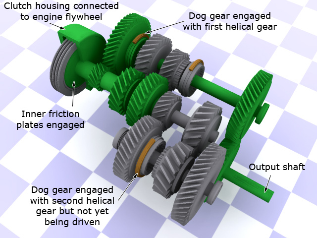
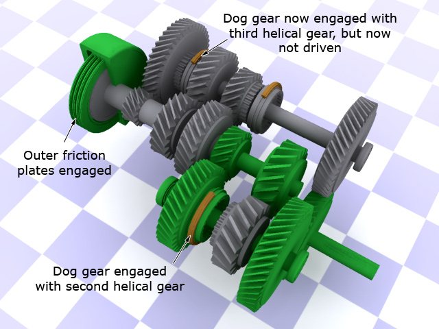
So how does this work? Well a DSG gearbox has one layshaft like a normal gearbox, but two output shafts that mesh to a third shaft which goes to the differential. One output shaft has 1st, 3rd and 5th gears on it whilst the other has 2nd, 4th and 6th. The layshaft is actually two shafts one inside the other connected to two concentric 4-plate basket-type clutches at the end. In first gear, one clutch is engaged and the central layshaft is connected to the engine. Selector forks have the first dog-gear engaged with the first helical gear and the car is moving forwards. At the same time though, on the second output shaft, the second dog gear is already engaged with the second helical gear. Because the outer clutch on the layshaft is disengaged though, there is nothing driving this second gear and the outer layshaft is simply spinning freely. At the point when the gearbox needs to shift up, it simply engages the second clutch at the same moment it disengages the first and the outer layshaft is now being driven from the engine. Because second gear was already engaged there is literally no delay in shifting so the gearchange is near instantaneous. Once in second gear, the inner layshaft is now freewheeling as the selector forks engage third gear on the first output shaft and so on and so forth.
 |
 |
 |
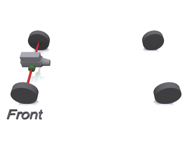
The three images here show my typical manual gearbox example modified into a 5-speed DSG. In the first image, first gear is engaged and second gear is pre-selected. The transmission of power from the engine to the output shaft is shown with the green components. The dual clutch (shown in cutaway) has engaged the inner set of friction plates which are connected to the outer layshaft. The first dog-gear is engaged with the first helical gear.
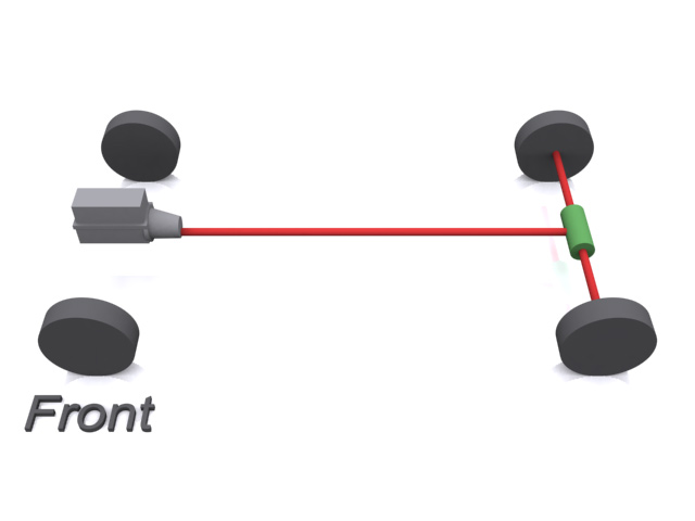
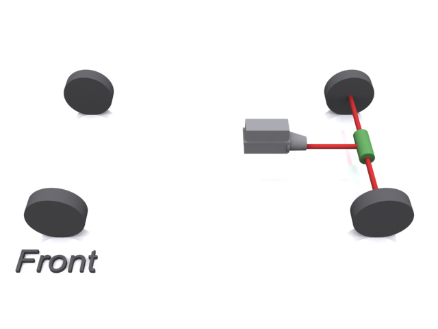
In the second image, second gear is selected and third gear is pre-selected. Again, the transmission of power is shown with the green components. This time the dual clutch has engaged the outer set of friction plates that are connected to the inner layshaft. The second dog-gear was already engaged with the second helical gear and so is now driving the output shaft.
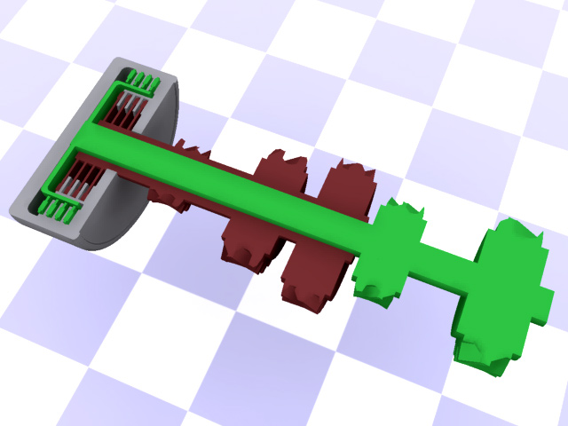
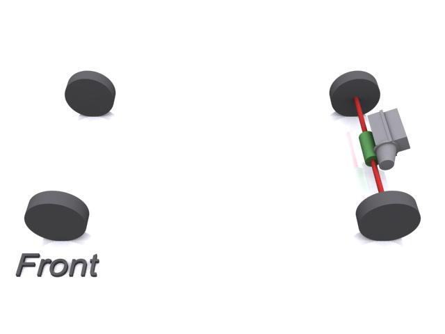
The final image shows a cutaway of a simplified dual-clutch, dual-layshaft so you can see how the friction plates, layshaft and gears all relate to each other. The green inner layshaft has the drive gears for second and fourth whilst the outer red layshaft has drive gears for first, third and fifth. The grey clutch housing contains all the springs and hydraulics used to engage the various clutch plates, although they're not rendered in this view.
CVT (continuously variable transmission) - what, why and how?
As they say in some circles, it's all downhill from here. Seriously. If you got your head around DSGs and automatic boxes, the rest of this page is going to be a veritable walk in the park, starting with the CVT - continuously variable transmission. CVTs are based on simplicity rather than complexity. Gone are the nightmare of spinning, whirling, intermeshing gears, cluches, clamps, bands, friction plates etc etc ad nauseum. Instead, the CVT essentially has three moving parts. No seriously. Read on.
If you live in the Netherlands, you're intimately familiar with the CVT - most brommers have a dry-belt CVT. For those unfortunate enough to have never lived there, a brommer is a small moped - typically less than 50cc in capacity. They're all two-stroke engines and they are uniquely identifiable from their sound - a constant pitched engine. No revving up and down, just a long, continous high-pitched drone, like bees on crack. It's a gorgeous sound. In fact the role that the Netherlands play in the CVT story is that dr. Hub van Doorne Invented the first CVT for automotive use in 1958. It was the Variomatic and it was used in DAF Cars Doornes Auto Factory.The first variomatic used rubber composite belts, but the durabilaty and strength of these belts just wasn't up to the job for serious car engines. This led to the development of a metal belt which allowed the normally slack side of the belt to actually push, and so was able to deal with higher torque values (up to 450Nm). The modern pushbelt is made up of hundreds of individual, specially designed steel elements, which are strung together along 2 high-alloy steel ring packs. Not so much of the rubber band any more. This product was sold by a new company by dr. Van Doorne - VDT - van Doornes Transmissie (transmission). In 1995 German multinational Robert Bosch Gmbh bought the VDT plant. In 2008, the stats for the factory were about 1100 employees producing about 2.4 million pushbelts. Nissan, Toyota, Mitsubishi, Hyundai, Jeep, Mercedes and Subaru are some of the manufacturers now employing CVTs although not all of them are buying direct from Bosch. Some buy belts produced under license by other transmission manufacturers such as JATCO, Fuji Heavy Industries (Subaru) and Punch. Japan is today's biggest market for pushbelt CVT's. Bosch have a CVT Pushbelt promo video available if you're interested.
But I digress. In 2005 CVTs really moved into the mainstream when Nissan introduced the "no shift shock" gearbox into their cars and SUVs. This followed a somewhat faltering start from Ford in 2004 who, frankly, botched the launch of their CVT so badly that barely anyone remembers it. So what the hell makes it so attractive to the automotive and motorcycling markets? Well apart from the simplicity, it has one extremely sound engineering principle: get the engine to peak torque and keep it there whilst infinitely varying the transmission. That way the engine is always performing at peak capacity. No changing gears, no revving up and down the rev range, and as Nissan so aptly put it - no shift shock.
Interesting factoid: CVT's were banned from Formula 1 in 1994 because they were making the cars too fast...
Two pulleys and a belt. It really is that simple.
So how does this magical CVT work? Simply. Very simply. The most basic CVT has two variable pulleys and either a steel-core rubber pull-belt or a steel alloy push-belt. One pulley is connected to the flywheel and the other to the gearbox output shaft. The belt loops around between the two. On simple scooter-type CVTs, the pulleys change geometry simply by rotational forces - the faster the engine pulley spins, the more it closes up and the faster the output pulley spins, the more it opens out. In automotive applications, the geometry of the pulley is governed by a hydraulic piston connected to the ECU. The pulley itself is basically a splined shaft with a pair of sliding conical wedges on it (called 'Sheaves'). The closer the wedges are together, the larger the radius 'loop' the belt has to make to get around them. The further they are apart, the smaller the radius 'loop' the belt has to make. Based on the principles established right at the top of the page when I was talking about intermeshing gears, if the flywheel pulley has a small radius and the output pulley has a large radius, then the transmission is essentially in low gear. As the car gets up to speed, the two pulleys are adjusted together so that they present an infintely changing series of radii to the belt which ends up with the flywheel pulley having the largest radius and the output pulley having the smallest. On then to the pictures.
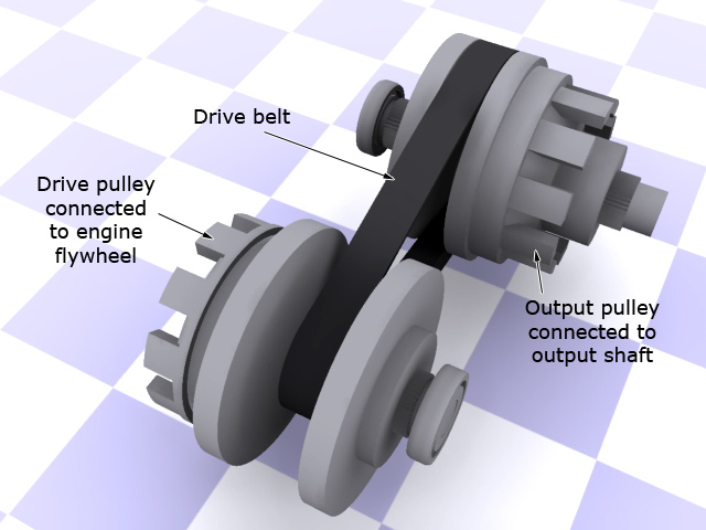
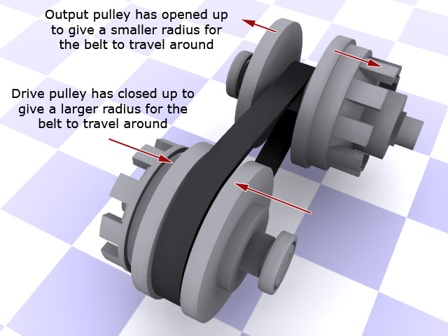
The image on the left shows the basic layout of a pulley-based CVT with the two sliding pulleys and the drive belt. This is the equivalent of 'low gear' - the drive pulley spins two or three times for each rotation of the output pulley. It's the equivalent of a small gear meshing with a large gear in a regular manual gearbox.
The image on the right shows the same system in 'high gear'. The drive pulley has closed up forcing the drive belt to travel a larger radius. At the same time, the output pulley has pulled apart giving a smaller radius. The result is that for each turn of the drive pulley, the output pulley now spins two or three times. It's the equivalent of a large gear meshing with a small gear in a regular manual gearbox. The difference here is that to get from the low gear to the high gear, the infinite adjustment of the position of the pulleys basically means an infinite number of gears with no point where the drive is ever disconnected from the output. Sweet.
Toroidal CVT (Nissan Extroid)
As good as a belt-driven CVT is, the weak link is the belt. If it gets damaged in any way, the transmission becomes useless. Another solution then is the toroidal CVT which is equally as simple in operation but has parts which are less prone to wear than the belt-drive type. With a toroidal CVT, both the input and output shafts are sculpted metal discs that face each other. In between are two rollers that free-wheel on their x-axis, making contact with both discs. The position of the rollers is controlled hydraulically and they pivot in their z-axis around a common centre so that wherever they are in their rotation, the rollers always touch the discs. Because the position of contact changes on the discs, the relative rotation of each disc changes.
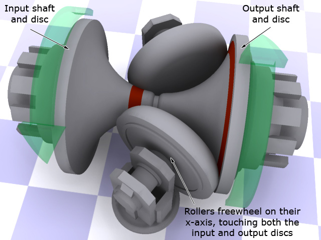
The image to the left shows a toroidal CVT in low gear. The input shaft is on the left. As it spins, the rollers make contact on the surface of it in the area I've shaded red. This spins both rollers on their x-axes, and because they both touch the output disc, it is spun in turn. The contact area on the surface of the output disc scribes a much larger circle - again rendered in red. Going back to the most basic stuff you learned earlier, this is the equivalent of a small gear driving a large gear - the gearbox is effectively in low gear.
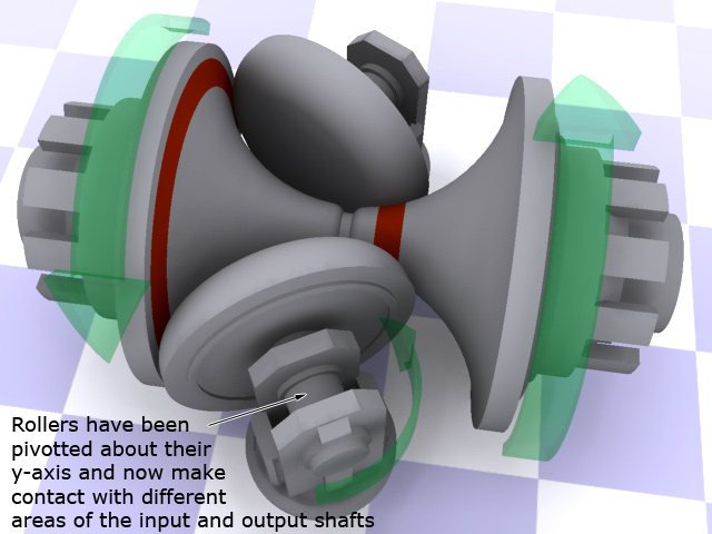
For a toroidal CVT to increase the output shaft speed, both the rollers are pivotted slowly about their y-axes. As they do this, their point of contact on the input and output discs changes in an infinitely smooth, continous motion. Effectively, the radius of the path on the input disc gets larger and larger as the radius of the path on the output disc gets smaller and smaller. This creates and infinite number of gear ratios until 'top gear' is reached when the rollers are in the opposite position to where they started. Now you can see the equivalent of a large gear driving a small gear - the gearbox is effectively in high gear. (right)
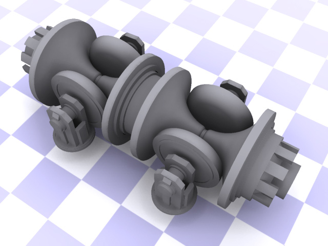
This type of infinitely adjustable toroidal CVT can deal with very high torque figures and can be stacked up end-to-end to provide other gearing options, and is essentially how the system in some of the JDM and Nissan home-market and CVT gearboxes works (think Skyline 350 GT-8). This last image shows a double-toroidal Nissan Extroid CVT configuration.
Like the site? The page you're reading is free, but if you like what you see and feel you've learned something, a small donation to help pay down my car loan would be appreciated. Thank you.
Differentials - they're why you can turn corners
With one or two exceptions, every car has a differential. This was a great surprise to an insurance adjuster I spoke to a few years back when he came to process a claim. He eloquently informed me that my claim was being rejected because my car didn't have a differential to replace. In the following few paragraphs you'll learn why that loss adjuster was talking bollocks.
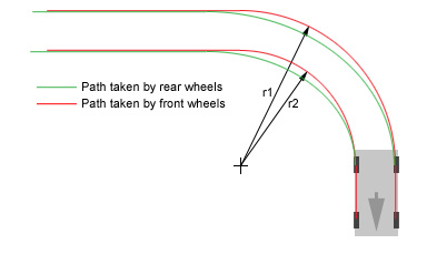
So how best to begin to talk about differentials? I suppose to start with you need to understand a very simple concept to do with circles. When you make a car go around a corner, the outer wheels travel further than the inner wheels. Have a look at the diagram here to see what I'm talking about.
The first thing you'll notice is that the rear wheels take a different path to the front wheels, but the other thing to notice is that because the car's wheels are describing different radius arcs, the further away from the centrepoint of the arc, the larger the distance that gets travelled. In car terms, that means the outer wheels need to turn more times than the inner ones every time you go around a corner, because they're describing a larger arc. The brighter ones amongst you will now have figured out that if the outer and inner wheels were joined together with a solid axle, one of them could not turn more times than the other - they'd have to turn at the same rate. That, dear reader, is the crux of the matter. Differentials basically allow two wheels on the same axle to turn at different rates. (As well as allowing the wheels on the same axle to turn at different rates, the differential also acts as the final gear reduction in the driveline.)
Is there a differential on each axle?
That depends. On a two-wheel-drive car, no. Only the driven axle needs a differential. The undriven wheels are not connected to each other so the differential is a moot point. For four-wheel-drive or all-wheel-drive vehicles, then yes, both the front and rear axles will have differentials because they are both driven axles. Technically, a differential is a torque-splitter - it splits the input torque two ways to two output shafts, each of which can turn at a different rate. For full-time all-wheel-drive, there is often a third differential in the driveline from the front to the rear of the vehicle, to allow the entire front and rear axles to spin at different speeds to each other. The difference between the various drive systems is illustrated later on this page in the section on 2WD, 4WD and AWD.
Open Differentials
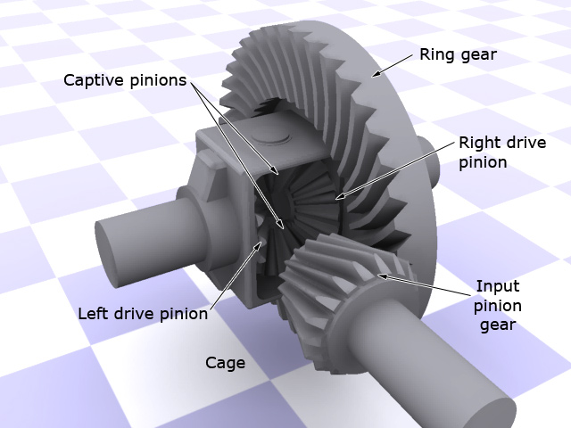
We'll deal with open differentials first because they're the easiest to explain, they're the most common, and they supply the same amount of torque to each output. Open differentials have a few essential components, illustrated below. The input pinion gear is the gear that is driven from the drivetrain - typically the output shaft from the transmission. It drives the ring gear which, being larger, is what gives that final gear reduction I mentioned. Attached to the ring gear is the cage, containing two captive pinion gears that are intermeshed with the two output pinion gears, one connected to each axle. The captive pinions are free to rotate how they wish.
As the input pinion spins, it meshes with the ring gear. The ring gear spins, spinning the cage and the two captive pinions. When the vehicle is travelling in a straight line, neither drive pinion is trying to spin any differently from the other, so the captive pinions don't spin and the turning of the ring gear is translated directly to both drive pinions. These are connected to the driveshafts to the wheels, so effectively, the ring gear spins the wheels at the same speed that it is turning. When the vehicle starts to turn a corner, one of the wheels is going to want to spin more quickly than the other. At this point, the captive pinions come into play, allowing the two drive pinions to spin at slightly different speeds whilst still transmitting torque to them. Clever. You can tell if your vehicle's differential is working properly by jacking the driven axle up off the ground and spinning one wheel. When you do, because the gearbox is stationary, it holds the ring gear solid, the captive pinions spin in opposite directions, and the other wheel on the axle spins the other way around. This also explains why a two-wheel-drive vehicle can get into trouble when one wheel has less friction with the ground than the other. The open differential cannot compensate for this. If one drive pinion is held solid compared to the other, then all the input gets redirected to the drive pinion that has the least resistance. This is why when you gun a two-wheel-drive car with one wheel on ice and the other on the road, the wheel on the ice spins and the wheel on the road doesn't. You don't go anywhere because all the engine power is directed to the wheel with least resistance - the one on the ice.
Imagine the same scenario on a four-wheel-drive vehicle that has open differentials on the front and rear. If you're off-roading in such a vehicle and get it into a situation where one front wheel and one rear wheel are off the ground, you're stuck. The differentials will spin the airborne wheels and send no torque to the ones on the ground. That leads us nicely on to the next topic :
Limited-slip differentials
Sometimes known by the "positraction" moniker, the simplest form of limited-slip differential is designed to combat the scenario outlined above. Physically there's not a lot of difference in the design of a limited-slip differential. It still has all the components of an open differential but there is two crucial extra elements. The first are spring pressure plates which are a pair of springs and pressure plates nestled in the cage between the two drive pinions. These push the drive pinions outwards where the second extra element comes into play - clutch packs. The backside of the drive pinions have friction material on them which presses against clutch plates built into the cage. This means that the clutch is always going to try to behave as if the car was moving in a straight line by attempting to make both output pinions spin at the same speed as the ring gear and cage. However, when a car with a limited-slip differential goes into a corner, there are enough forces at play that the drive pinions begin to slip against the clutch material, thus allowing them to turn at different speeds again. The stiffness of the spring pack coupled with the friction of the clutch pack together determine the amount of torque required to overcome the clutch.
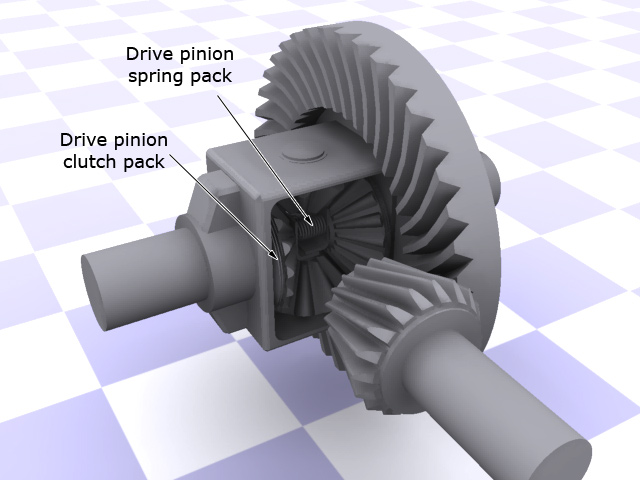
So lets go back to our hapless driver stuck with one wheel on the ice and another on the road. With a limited-slip differential, because of the spring- and clutch-packs, even though one wheel is on the ice, the differential is going to attempt to spin both drive pinions at the same speed. With low engine revs and steady throttle control, the wheel on the road will get enough spin to move the vehicle forwards. If the engine is revved hard though, it can still generate sufficient torque to overcome the clutch pack and once again, only the wheel on the ice will spin. To get around this, it's a good idea to try to pull away in second gear - that gives the limited-slip differential a chance to do its job. The render here shows the generic open differential from above modified to be a limited-slip differential.
Torsen differentials
Torsen differentials are a derivative of open differentials. They derive their name from their function - Torque-Sensing. When the torque going to both outputs is the same, a Torsen differential essentially works just like an open differential. The change comes when the torque going to each output begins to change, for example as a result of a slippery road surface under one wheel. When this happens, what's known as an Invex gear train (inside the differential) begins to bind together.
The Invex gear train is designed with a torque bias ratio in mind that determines the ratio of torque that it can split between the outputs as the geartrain begins to bind together. A 3:1 Torsen differential, for example, can deliver three times the torque to the output that has more traction. The downside of this is that if one output suddenly ends up with no traction at all, the differential won't be able to supply any torque to the other output. Using the 3:1 example, one output can have up to three times the torque than the other. If one output has zero traction, then three times zero is zero, so the other output also gets no torque. That's a gross simplification of how the system works too. If you're really interested, Torsen Traction have some good engineering articles on their website.
Torsen differentials are normally used in-line between the front and rear drives for performance all-wheel-drive vehicles, to split the torque between the front and rear axles, rather than the left and right wheels.
How does a Torsen 'sense' torque?
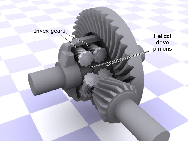
The Invex geartrain is essentially a set of helical-cut gears that all mesh together and torque-sensing is actually a bit of a misnomer. The Torsen differential is an entirely mechanical affair with no clutches, hydraulics, actuators or sensors. It doesn't really 'sense' anything. If you look at the rendering above, you can see the Invex gears mesh with the helical drive pinions. At the ends of the Invex gears are regular-cut gears that mesh with each other. So in this example, looking at the top pair of Invex gears; the left gear meshes it's helical-cut part with the helical left drive pinion, and it meshes it's regular-cut part with the right Invex gear. That gear in turn meshes its helical-cut part with the right helical drive pinion. It's this interconnectivity that allows the Torsen to work like an open differential when the torque is even, but as a torque-sensing unit when its not.
Where the helical cuts mesh together (shown in close-up in the rendering on the right), there's a certain amount of friction inherent in that design. The angle of the helical spiral used to create the gears determines the amount of force required to make them turn. The shallower the pitch of the spiral, the more force required, and hence the more torque required to turn two meshed gears. That's the clever part then - the spiral pitch. The precise spiral pitch angle determines the torque bias ratio.
The whole system works on simple high-school physics. Remember the experiment where you had two blocks of wood with sloped cuts and you had to determine the downward force required to make the top block slide along the slope of the bottom block? It's the same principle. The steeper the slope, the less force required to make the block slip. With helical gears, the steeper the pitch of the spiral, the less torque required to make them mesh together.
Locking differentials
Locking differentials are another derivative of open differentials but with an electronic, pnuematic or hydraulic actuation system that locks the two drive pinions together as if they were a solid axle. This is for use in serious off-roading, where a vehicle will spend a lot of time with one wheel per axle in the air. By locking the differential, it behaves like a solid axle and both wheels are spun together.
The exceptions that prove the rule
Remember I said that there were a couple of exceptions? A good example of a vehicle with no differential would be a NASCAR or Indy car racer. To save weight, those cars have no differential. "Ah yes," I hear you say, "but they go around corners so they must have differentials!". Well - yes, and no. With the exception of street courses, NASCAR and Indy car racers always turn left, and this is Good News for the engineers. When you know that a vehicle is always going to be turning one direction, you can make the outer tyres physically larger than the inner ones. This gives them a greater circumference, and that in turn means that for every turn of the axle, the outer tyre is going to try to travel further than the inner one - precisely what you need in a corner. For the straights, these racers live with the scrubbing that happens when the tyres try to travel different distances because 90% of the time they are cornering.
AWD couplings
Viscous couplings
Viscous coupling aren't really a type of differential but they're worth mentioning because they're used a lot in all-wheel drive vehicles. Lower end AWD vehicles are actually mostly 2-wheel drive vehicles (see the article below for all the differences) until the front wheels begin to slip. When that happens, they become all-wheel-drive through the use of a viscous coupling. In it's most simple form, it's essentially identical to the torque converter found in an automatic gearbox. For a full description of how that works, see torque converters up above.
Hydraulic clutch couplings
Again, not really a differential, but another type of device used in AWD cars to engage the rear differential. With these types of coupling, the front and rear differentials drive hydraulic pumps - normally filled with oil. Any difference in the speed of the two pumps causes a pressure imbalance in the system that activates a clutch pack in-line to the rear differential to engage it. So again, when the front wheels spin faster than the rear (meaning slip), the clutch pack is engaged and the rear differential comes into play. These types of coupling typically also have braking and thermal overrides so that if the gearbox oil in the rear differential becomes too hot, or the car is braking, the clutch pack can be overridden and disengaged (without this, ABS-equipped vehicles would not be able to sense all four wheels correctly under braking).
Like the site? The page you're reading is free, but if you like what you see and feel you've learned something, a small donation to help pay down my car loan would be appreciated. Thank you.
2WD, 4WD, AWD
Ok so in the last couple of pages you've now seen a lot of references to 2WD (two-wheel drive), 4WD (four-wheel drive) and AWD (all-wheel drive). Time to explain the differences.
2WD - two-wheel drive

This is by far the most common type of drivetrain in any car today. The engine drives the gearbox which sends its output to an open differential either on the front or rear axle, which in turn drives those wheels. If one of the driven wheels comes off the ground, or gets on a slippery surface like ice, the car gets stuck because all the torque is being sent to that wheel whilst the other three sit there helpless.
4WD - four-wheel drive
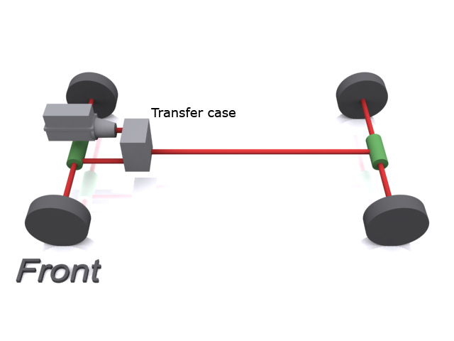
Also known as part-time all-wheel drive, this system has an open differential on the front and rear axle and a transfer case on the output from the gearbox. Typically 4WD is normally driving the rear axle with the front axle only coming into play in 4WD mode. The transfer case is the device that splits the torque between the front and rear axles. It typically has some sort of selectable internal differential or viscous coupling to allow the front and rear drives to turn at different speeds if need be. Some trucks and SUVs have a selector with 2H, 4H and 4L on it - it looks like a second gear shift. This is actually controlling how the front and rear outputs of the transfer case get locked together. In 2H mode (2-wheel drive, high), it essentially disconnects the front output completely and only drives the rear axle. In 4H mode (4-wheel drive, high), it engages the front output via the viscous coupling so that the axles can turn at different speeds, and now sends torque to both open differentials. In 4L mode (4-wheel drive, low) it engages a second set of reduction gears and locks the front and rear axles together so they must spin at the same speed. This would be bad for on-road driving because it does not allow any difference in speed between the front and rear wheels, so you'd often get dragging and slipping which would make the car essentially unsafe to drive. However, locking everything together like this and reducing the gear ratio makes perfect sense for off-roading, which is why it's an option. However, with open differentials, it's still entirely possible to get stuck with a 4WD vehicle. If you're off-roading and the front-left and rear-right wheels both leave the ground together (for example), then the torque will all be sent to those wheels and they'll spin helplessly in the air. Locking, limited-slip or Torsen differentials solve this but add weight, complexity and cost to the system.
Locking hubs On older 4WD systems, the front wheels could only be engaged to the transfer case by locking hubs. Essentially the transfer case was always sending torque to the front driveshaft and had no viscous coupling. To get into 4WD mode, the driver had to stop and get out, and lock the front wheels to the axles so they could be driven. In newer 4WD systems, the lockable hubs are still present on some models, but are designed more for mechanical sympathy and fuel economy than anything else. With the hubs onlocked, the whole front part of the drive system isn't being dragged along for the ride, which causes mechanical wear and a drop in fuel economy.
AWD - all-wheel drive type 1
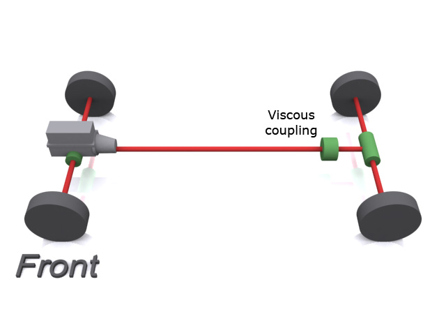
Finally, all-wheel drive or full-time 4WD. Found mostly on sportier cars, but also on some SUVs, there are two types of AWD, both designed to try to overcome the problems with 4WD. The simplest form has two open differentials - one on each axle - and a viscous coupling between. The engine drives the gearbox which drives two output shafts. One goes to the front open differential and the other goes to the viscous coupling, the output of which is connected to the rear open differential. Under normal conditions, this type of AWD system functions exactly like a 2WD car, driving only the front axle (unlike a 4WD which normally drives the rear axle). Lower end Subarus and some of the Honda trucks use this system. The front wheels turn at a certain rate, and the rear wheels are dragged along for the ride. Both halves of the viscous coupling are spinning at the same speed so no torque is sent to the rear axle. If the front wheels begin to slip and spin, the input to the front of the viscous coupling begins to spin faster than the rear and because of its torque-converter-like design, this causes the rear output to want to speed up. At this point, the drivetrain is now transferring torque to the rear axle and the car starts to function in AWD mode. Actally, AWD is a bit of a misnomer at this point, because unless the car has limited-slip differentials front and rear, it's still only really driving two wheels in this mode - the one on the front and the one on the rear axles that have the most traction. That leads us nicely on to.....
AWD - all-wheel drive type 2
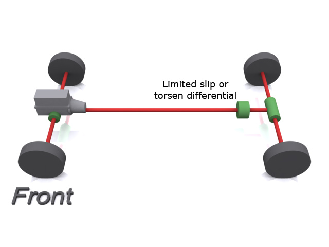
This is the other type of AWD found on higher-end Subarus, rally cars, expensive sports sedans and such. Very similar to the type 1 AWD, it replaces the viscous coupling with a Torsen differential, and replaces the open differentials front and rear with either Torsen or limited-slip differentials. This is the only true all-wheel-drive system because it will always drive all four wheels. It's also bloody expensive and it saps gas-mileage because of all the extra drag induced in the driveline. But then if you're into performance off-roading, gas-mileage really isn't your primary concern.
FWD, RWD, FE, ME, RE
Not to be confused with the descriptions aboe, these acronyms determine the engine location and driven axle(s) on a car.
FWD = front-wheel drive.
RWD = rear-wheel drive.
FE = front engine.
ME = mid engine.
RE = rear engine.
The position of the engine, being the heaviest part of the car, affects how the car handles. Most vehicles are front-engined, front-wheel drive (FE-FWD) with the engine, gearbox and differential all clustered together in one place.
BMWs and other higher-end vehicles are front-engined, rear-wheel drive (FE-RWD) with a propshaft going from the gearbox and engine at the front to the differential at the rear.
Sports cars like the Toyota MR2 and the McLaren F1 are mid-engined. Putting the engine as close to the middle of the car as possible gives the best possible front-to-rear weight distribution and gives predictable, even handling. Mid-engined cars are typically rear-wheel drive (ME-RWD).
Finally, rear-engined vehicles such as most Porsches and the original VW Beetle have the engine, gearbox and differential all clustered at the rear of the car and are typically rear-wheel drive (RE-RWD). The downside of this is that when cornering, with that much weight at the back of the vehicle, it can behave like a pendulum and induce chronic oversteer in corners.