
The car Transmission Bible - how transmissions and gearbox work including manuals, automatics, clutch, CVT, crash gearboxes, differentials, limited-slip differentials, 2wd, 4wd, awd and much more.
The Transmission Bible
Sequential gearboxes - what, why and how?
If you've ever watched motorsports you'll have noticed that the drivers don't have an "H" gate for their gearstick. They either jam the stick back and forth or use paddle-shifters behind the steering wheel. The paddle-shifters do the same job as the gearstick movement in this case, only using electronics to move the shifter. So what's going on in a sequential gearbox? Actually it's quite simple. A sequential gearbox is just like a manual gearbox but the selector system is different. The manual gearbox example at the top of the page showed a series of selector forks which were moved by the physical position of the gearstick. In a sequential box, those selector forks are connected to a single shaft that has corkscrew-type grooves in it. The collar that fits around this selection shaft has a ballbearing in it which sits in a recess in the collar as well as in one of the corkscrew grooves.
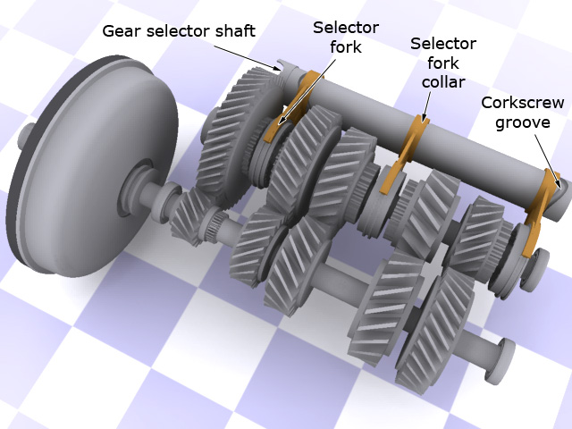
When the gearstick is moved forwards or backwards, the selector shaft is mechanically turned by some number of degrees. That twisting motion rotates the corkscrew groove which in turn interacts with the ballbearings and the selector fork collars, forcing them to slide back and forth. Each click of the gearstick rotates the shaft another number of degrees and all the selector forks change position in one go. That's why it's called a sequential gearbox - the gears are always selected in sequence. You can't jump from first to third, you have to go via second. Often, sequential gearboxes have a "double-click for neutral" option and when you do this, it disengages the clutch and rotates the selector shaft back around to the neutral position, just before first gear. So why design and use a sequential gearbox? Well for a start it's a simpler design than a fully-manual gearbox with less moving parts. For racing drivers it makes for much quicker gearchanges - bang the gearstick and you're up a gear nearly instantly.
If you want to see how the corkscrew groove interacts with the selector collars this animation is worth watching.
Trivia note : TipTronic type gearboxes are not sequential. See the section below for an explanation of why.
One final point on sequential boxes - if you've ridden a geared motorbike in the last 50 years or so, you've used a sequential gearbox. Most bikes are 1-down, 5-up with neutral in between first and second gear. That little gear selector pedal that you click up and down with your left foot is simply linked to a ratchet system that ratchets the selector shaft around to pick the relevant gear.
Automatic gearboxes - what, why and how?
If you're reading this in America, there's a fair chance that everything above this point in the page was totally useless to you because you don't "drive stick", you drive an automatic. Automatic gearboxes are a totally different beast. For a start they don't have a clutch pedal. For that matter they don't have a clutch at all; they have a torque converter, but we'll get on to that later.
If you took an automatic gearbox apart (and for the love of all that is Holy, please don't), you'd see an enormous collection of mechanical parts all jammed into an impossibly small space. Taking centre stage would be the planetary gearset. Not to be confused with planetary drive, a hyperspace system we've only seen on the Sci Fi channel, the planetary gearset is nowhere near as exciting. In a manual gearbox, the dog gears lock and unlock different sets of helical gears to the output shaft in order to give the various gear ratios. In an automatic gearbox, the planetary gearset produces all the different gear ratios in one go and with only one set of gears. Ok so maybe it is pretty cool, but know this - an automatic gearbox is several orders of magnitude more complicated than a manual gearbox. Read on and you'll begin to understand why getting an automatic gearbox overhauled costs so damned much.
A quick primer on how planetary gearsets work
Any planetary gearset has three main components. The sun gear, the planet gears (and their carrier) and the ring gear. Any one of these three components can be locked in place, but more importantly, any one can be the input or the output drive. Locking any two of them at the same time will always produce a 1:1 gear ratio. So how the hell does that work? One set of gears for every ratio you need? The work of the Devil? Time to get the old brain massager out again. For this example I'll talk about a planetary gearset with a ring gear that has 75 teeth and a sun gear that has 25 teeth. The following table shows how sending the input to one set of gear and locking another set can give a wide variety of gear ratios.
| Input | Ouput | Locked gears | Calculation | Resulting ratio |
|---|---|---|---|---|
| Sun | Planet Carrier | Ring | 1+(Ring/Sun) | 4:1 |
| Planet Carrier | Ring | Sun | 1/(1+(Sun/Ring)) | 0.75:1 |
| Sun | Ring | Planet Carrier | -Ring/Sun | -3:1 (ie. reverse) |
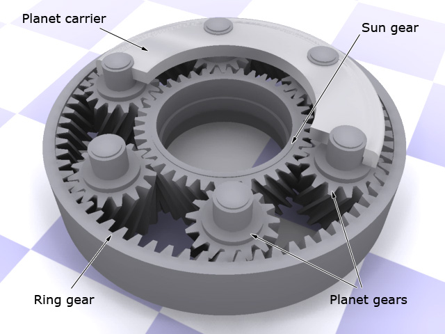
So that table basically has one reverse and two forward gears. Need more gears? Add more planetary gearsets with different numbers of teeth and link them together. Make the ouptut of one become the input of another and you can start to multiply up the number of gears available to you. The image here shows an example planetary gearset with the planet carrier in cutaway.
Again, something like this works much better in motion. Below I've rendered an animation showing a planetary gearset in motion. In this example, the blue ring gear is locked. The input is the yellow sun gear and the output is the planet carrier. The planetary gears are the green ones, and the planet carrier is semi-transparent so you can see what's going on inside. This shows clearly how the input to the sun gear can be geared down - in this case by a ratio of 2.7:1.
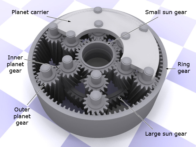
Compound planetary gearsets In reality, automatic gearboxes typically use one or more compound planetary gearsets instead of chaining regular gearsets together. They look just like a regular planetary gearset from the outside, but inside there are two sun gears and two sets of intermeshing planet gears. There is still only one ring gear though. With a single compound gearset, the number of ratios available increases to 4 forward ratios and one reverse. The image below shows an example compound planetary gearset again with the planet carrier in cutaway. In my example, the planet gears are arranged as inner and outer planets. The inner ones are shorter and only engage the small sun gear and the outer planet gears. They in turn engage the larger sun gear at the bottom and the outermost ring gear. Another configuration would be to have the two sets of planet gears next to each other but slightly staggered so that only one set meshes with the ring gear. Would you believe there are people paid to come up with this stuff? Makes you wonder if you shouldn't just accept that an automatic gearbox simply works and that you don't want to know why.
I could now go on to explain to you how all the different ratios get selected but if I did, I'd lose most readers at this point and all the typing and fine imagery in the rest of the page would go to waste. For the sake of a working example, I will explain the first two gears though.
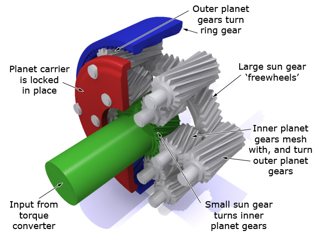
Looking at the images here, When first gear is engaged, the smaller sun gear (green) is driven from the torque converter. The planet carrier (red) tries to spin the opposite direction but because of a one-way clutch system, it locks in place which forces the ring gear (blue) to turn instead. The ring gear becomes the output from the gearbox in this case and there you have first gear. The catch is that because of the design of the compound gearset, the direction of rotation of the output shaft ought to be opposite to that of the input shaft, but it isn't. This is because the first set of planet gears engages the second set and it's the second set that turns the ring gear. Doing this reverses the direction of rotation, thus making it now the same as the input shaft.
Moving swiftly along, when second gear is engaged the input is again the small sun gear but this time the ring gear is held in place by a band and the output becomes the planet carrier.
Locking planetary gearset components
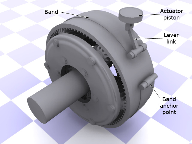
If you've got this far, congratulations, you're doing better than I did the first time I had automatics explained to me. You might now be wondering how the clutches and bands I've mentioned above actually work. Bands are literally that - they're a band wrapped around the outside of the ring gear and when tightened, they lock the ring gear in place. Bands are actuated by a lever or pivot connected to a small hydraulic piston in the gearbox housing. The image here shows how a band might work in the example I've been building up. The actuator piston actually sits in a small cylinder inside the hydraulic distributor (see later) which is built into the gearbox case. You can see the band wraps around the ring gear and when the piston is pushed down, it tightens the band and clamps the ring gear into place, locking it to the gearbox case.
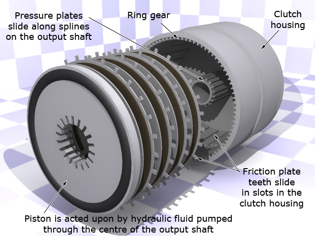
The clutches are a little more complex and are used to perform functions such as locking the sun gears to the turbine or input shaft. Automatic transmission clutches are a lot like the motorbike basket clutches mentioned higher up the page. They consist of a series of pressure and friction plates with splines on the inside and outside. These are compressed by hydraulic fluid fed through channels in the various shafts to a clutch piston. Clutch springs make sure the clutch piston releases when hydraulic pressure is reduced. The example here shows how a clutch system might work to lock the ring gear to the output shaft.
The automatic gearbox hydraulic system - how it changes gears.
You've got the idea by now that hydraulics are used a lot in an automatic gearbox. They're used to pressurise the piston plate for the clutches and they're used to move the band-activation pistons up and down. In the good old days, the routing of the hydraulic fluid in the system was controlled by mechanical shift valves linked to the throttle valve on one side and the governor (see later) on the other. Those days are on the way out now and generally speaking, when you move the gear stick, you're doing nothing more than giving an input to the engine management system or engine control unit (ECU) indicating what gear you'd like to be in. The ECU then looks at engine speed, speed across the ground, current gearbox configuration and position of the gear selector and decides what the best action is. It signals solenoid shift valves inside the hydraulic system to open and close appropriately and the gearbox then changes gears as necessary.
But how does the gearbox know to go up gears when you're speeding up, and down when you're slowing down? Well there's a device called the governor attached to the output shaft of the gearbox. It's a centrifugal sensor connected into the hydraulic circuit. The faster you're going, the faster the governer spins and the more open the valve in it becomes. That in turn allows the pressure of the hydraulic circuit to rise, which then applies more pressure to different components, pistons and clutch activators and lets the gearbox shift up at the right speeds. Again, in modern cars, all this information is fed through the ECU which also takes another input from a throttle sensor or more usually a vacuum modulator. These devices allow the ECU to know how hard the engine is working - something else that's critical to how the gearbox operates. It's these inputs that can sense the sudden need for more power so that when you stuff the accelerator to the floor, the gearbox can downshift. The ECU sees a relatively sedate output shaft speed from the governor but a sudden and dramatic increase in vacuum pressure in the engine intake manifold. This is the key to dump the gearbox down a gear to get more power and quick.
Limiting gear selection. Most gearbox selectors have a '1' and '2' position. When you select one of these positions you're inhibitting the gearbox's ability to pick any gear higher than that. In a mechanical system it locks off certain portions of the hydraulic system physically so the gearbox simply cannot provide hydraulic pressure to the selector components. In a modern electronic gearbox, again you're simply telling the ECU "don't select anything higher than this". The ECU will then simply not ever send commands to open the solenoid valves to activate higher gears.
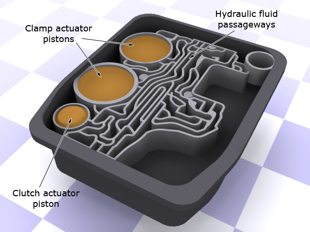
The pump. It's probably no surprise to you that all this hydraulic trickery needs some sort of pressure to work and that comes from the hydraulic pump. This is normally located in the cover of the gearbox housing itself and it draws fluid from the gearbox sump to feed the gearbox hydraulic system, the fluid cooler (basically a small radiator) and the torque converter. The pump itself is a typically a rotary displacement pump that uses the difference in pressure between the spinning centre lobe and the outer housing to suck fluid in on one side and expel it on the other.
For the uninitiated or the morbidly curious, the image above shows a highly simplified example of the rats nest of hydraulic routes in a gearbox housing. The hydraulic lines are effectively cast in the metal because doing it with rubber hoses and clamps would be so complicated and take up so much space that it would be uneconomical and unreliable to do in mass production.
Park it!
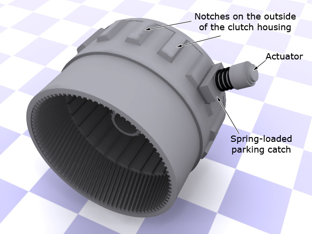
So after the long and complicated slog through all that stuff above, are you ready for something simple? Ok, here we go. "P" - the park position on an automatic gear selector. If you've ever engaged park right before you've actually stopped, you'll have heard a clicking sound followed by a thud as the gearbox locks and the car rocks forwards. The mechanism that does this is so disturbingly simple it's almost not worth rendering a picture for. Ready? How about notches on the outside of the clutch housing and a single or pair of spring-loaded catches? Seriously. The image here shows the basic idea behind the park mechanism in an automatic. When you put the gearbox in 'P' for park, the catches are deployed and they fit into the notches on the outside of the clutch housing. Simple.
Torque Converters
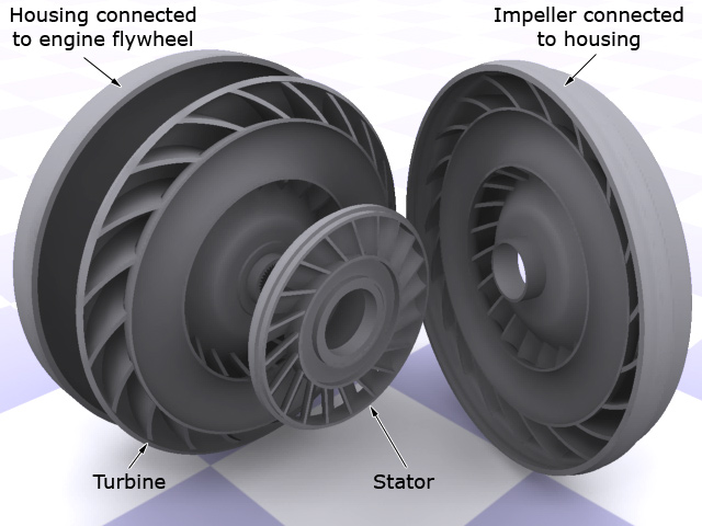
Just like a manual gearbox, an automatic gearbox needs a method of decoupling the constantly-spinning engine from the gearbox components. To do this it uses a torque converter which is a viscous fluid coupling (because it's full of hydraulic fluid). A torque converter consists of three basic elements. The impeller, the turbine and the stator. The impeller is attached to the torque converter housing which itself is attached to the engine flywheel. The impeller is basically a centrifugal pump. As the flywheel spins, so does the impeller and the vanes take the fluid from the central part of the torque converter and fling it to the outside creating a pumping action. The fluid then circulates around the outer edge of the torque converter and back into the turbine. The turbine is basically the opposite of the impeller - it's like a ships's propeller in that the fluid passing through it causes it to spin. The turbine is connected to the input shaft of the gearbox via a splined shaft so as the turbine spins, so does the input shaft to the gearbox. The fluid passes through the turbine from the outside towards the inside. Finally, as the fluid reaches the central core, it passes through the stator which is designed to help redirect the flow into the inner vanes of the impeller. (Without the stator, the whole system would be a lot less efficient) With this mechanism, the fluid is constantly being circulated. In the image here I've rendered the various parts of an example torque converter taken apart so you can see the internal construction.
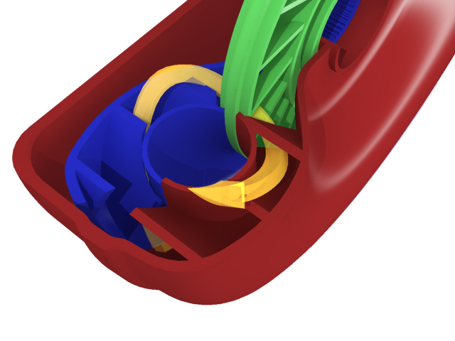
When the engine is idling, the fluid is pumping around without a lot of force and the amount of torque on the turbine is minimal. As you accelerate, the impeller speeds up and creates larger forces on the turbine which in turn spins more quickly and with more torque. Because it's connected to the input shaft of the gearbox, this feeds more rotational speed and torque into the gearbox and the car starts to move forwards. It's because of this viscous liquid coupling that automatic gearboxes have a certain amount of 'slop' in them - the engine can rev up and down without the car actually changing speed too much. It's also the reason automatics are less fuel efficient because the torque converter uses up energy from the engine simply in its design by spinning the hydraulic fluid. In the image here I've rendered a close-up cutaway of an assembled torque converter. The yellow arrow is my attempt to show the basic circulation path of the fluid inside as it is pumped from the impeller (red) through the turbine (blue) and back through the stator (green).
For sportier vehicles or those with specialised needs, some torque converters include a hydraulic clutch. Once the car is moving and in top gear, the clutch engages and locks the turbine to the impeller. Once that happens, the whole torque converter spins as one and the viscous coupling becomes redundant - effectively the gearbox now behaves like a manual because the engine flywheel is connected directly to the gearbox input shaft. By locking all the components together, it makes the car as fuel efficient as a manual when in top gear because the energy that was being used up in the viscous coupling is no longer required. It also means instantaneous throttle response - you push the accelerator and the car accelerates instantly just as with a manual.
But why is it called a torque converter? Very simply, because it has the ability to multiply the torque from the engine 2 or 3 times in certain conditions. Basically, from a standing start, when the engine is spinning far faster than the gearbox, the whole design allows the torque from the flywheel to be multiplied. As the car gets up to speed, the multiplication factor drops until it becomes 1x once everything is in motion and the impeller and turbine are moving at almost the same speed.
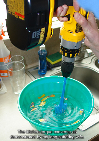
Doing it yourself. In true Blue Peter fashion, you can demonstrate the principle behind a torque converter at home. Get a large bucket or bowl and a cordless drill with a paint-stirrer. Fill the bucket with water and put some bits of paper around the outside of the bucket, floating on the water. Stuff the paint stirrer in the middle and pull the trigger on the drill. To start with, the paint stirrer is spinning way faster than the water in the bucket, and the bits of paper will barely be moving. As the water in the bowl begins to speed up its circulation, the bits of paper will being circulating the bucket at speed. Eventually the water in the bowl will be circulating at almost the same speed as the paint stirrer is turning. (At this point your wife/husband will probably also be complaining that it's going all over the kitchen/bathroom - you've been warned) It's that "almost" that shows the inefficiency in a torque converter - the fluid can never spin at exactly the same speed and thus it can never impart the exact same torque and motion into the turbine. Now imagine that the bucket or bowl has vanes around the inside of it. As the water is circulating, it's going to be applying force to those vanes and given a slippery enough surface, your bucket or bowl will eventually start to spin. Voila. The drill and the paint stirrer are the input from the engine and the spinning bucket or salad bowl is the output to the gearbox.
The other way to do this is to take two desk fans and turn one on and point it at the other. Eventually the second fan will start to spin because of the air being forced past it by the first fan. This uses the same principle but with moving air instead of water and it's nowhere near as much fun to watch 
Like the site? The page you're reading is free, but if you like what you see and feel you've learned something, a small donation to help pay down my car loan would be appreciated. Thank you.
TipTronic® Gearboxes
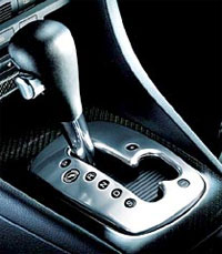
If you've owned a VW or Audi in the last few years it might have come with a TipTronic® gearbox. To you, the driver, it looks like a regular automatic gearbox but with with an H-gate for the gearshift. In normal operation, you use the gearbox just like an automatic, putting it in 'D' for Drive and just letting it go about its business. But if you click the gearstick over into the H-gate it becomes a discrete automatic, meaning you can then click it fowards and backwards like a sequential gearchange. In this mode you are basically telling the gearbox when you want it to shift rather than allowing it to shift for you. When you click it forwards for example, you're indicating a desire to go up a gear. The ECU looks at the engine speed, road speed, torque and load and if all the planets align, it shifts up by activating the relevant solenoid valves in the automatic hydraulic system.
Most TipTronic® designs do have a certain amount of idiot-proofing though, and if you try to rev the tits off the engine in first, it will override you and automatically shift up to second to save the engine. These types of gearboxes often have steering-wheel shifters either as buttons or triggers on the steering wheel (like the Mazda MX-5) or paddle-shifters. TipTronic® is actually a design from Porsche and they simply license it to other vendors, typically German manufacturers. Because it was one of the first designs to come to the mass market, this type of discrete automatic automatic gearbox is now often referred to as TipTronic® even if it isn't one of the VW/Audi/Porsche ones. Here's a non-comprehensive list of some of the manufacturers and their TipTronic® type shifts:
Acura: Sequential SportShift. Audi: Tiptronic, Multitronic (CVT). BMW: Steptronic. Chrysler/Dodge: AutoStick. Citroën: Sensodrive. Ford (Australia): Sequential Sports Shift. Honda: iShift, S-matic, MultiMatic. Hyundai: Shiftronic, H-Matic. Infiniti: Manual Shift Mode. Jaguar: Bosch® Mechatronic. Lexus: E-Shift. Mazda: Sport AT. Mercedes-Benz: TouchShift. MG-Rover: Steptronic. Mitsubishi: INVECS, INVECS II, Sportronic, Tiptronic. Nissan: Tiptronic. Vauxhall/Opel: Easytronic. Peugeot: 2Tronic. Pontiac: TAPshift. Saab : Sentronic. Subaru: Sportshift (system developed and name used under license from Prodrive Ltd.). Smart : Softip. Volkswagen : Tiptronic. Volvo: Geartronic
Semi-automatic Gearboxes
Despite the name, these are actually an advanced type of manual gearbox. It's better to refer to them as clutchless manual gearboxes because that more accurately describes what they are. Semi-automatics do not use planetary gearsets and torque converters; they use layshafts, output shafts, clutches and selector forks just like a manual. They come in three flavours, all of which have the same internal mechanisms. Two of those use the familiar paddle-shifters or up-down gearstick for changing gears. (This begins to explain why you cannot simply look at a gearstick or paddle-shifter and tell what the gearbox is. Up/down gearsticks or paddleshifters can both control sequential manual, clutchless manual or TipTronic® type gearboxes.) The third type has a pure manual gearstick. None of the three types have a clutch pedal though so how do they work? Well in the case of the first type, when you click the gearstick up or down, or press one of the paddleshifters, a hydromechanical system disengages the clutch and then moves the gearbox selector forks into the position for the next gear before re-engaging the clutch. Because the system takes inputs from load- and torque-sensors as well as road speed, throttle position and engine demand sensors, and because it's all computer controlled, it can shift more quickly and more smoothly that you or I ever could.
The third type uses the same hydromechanical system underneath but has additional sensors coupled to the gearstick. With this type, the action of moving the gearstick out of the gate for one of the gears (for example pulling it back from first) passes a hall effect sensor which tells the clutch to disengage. When you push the gearstick into the gate for the new gear, another hall effect sensor detects the final position of the gearstick and tells the clutch to re-engage. Effectively it's identical to driving a manual car only without a clutch pedal.
Clutchless manual gearboxes have appeared under many different names such as Saxomat and Olymat (Fiat 1800, Saab 93, some BMWs and Opels).