Car Bibles Blog
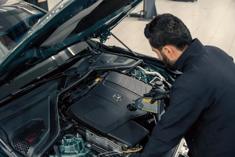
Observations on Engine Oil Preservation and Protection
Insights on Engine Oil Pressure Sensor Issues in Modern Vehicles
Head Gasket Failures: Real-World Insights on Symptoms and Solutions
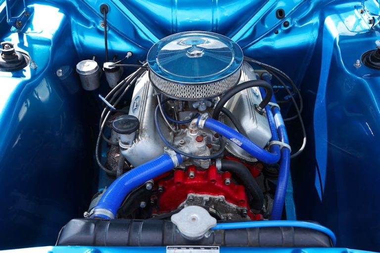
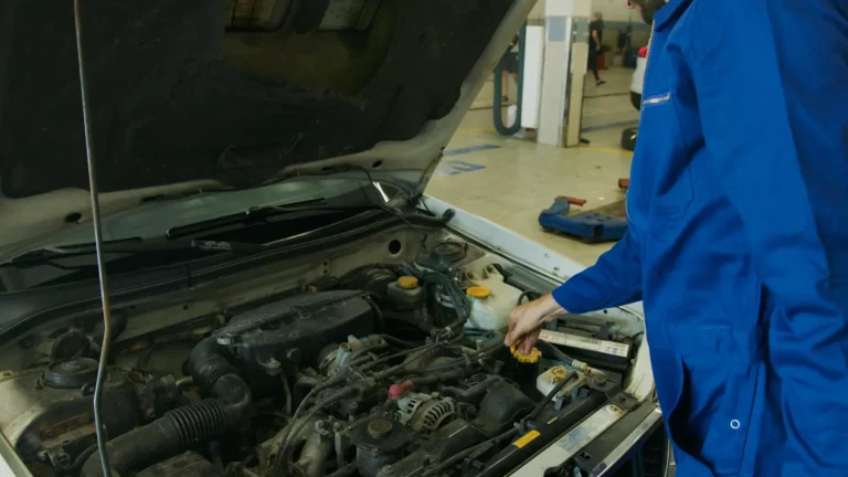
Engine Bay Maintenance: Observations from the Field

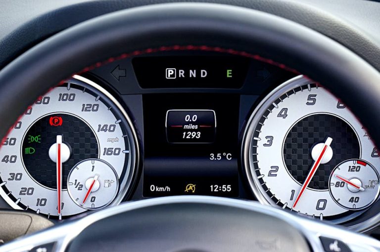
Common Causes of Vehicle Starting Issues and Their Implications

Observations on EGR Valve Failure Symptoms in Vehicles
The Role and Functionality of Engine Brakes in Modern Vehicles
Observations on Coolant Change Intervals in Automotive Systems
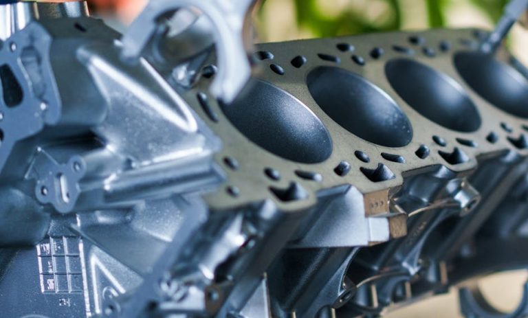
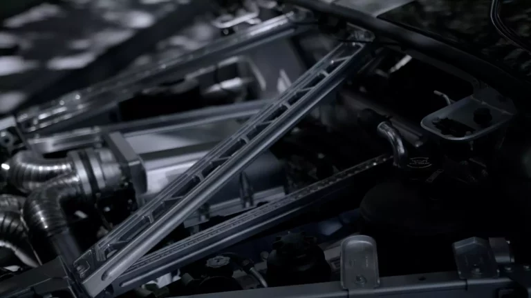
The Engine Block: Core Component of Automotive Powertrains

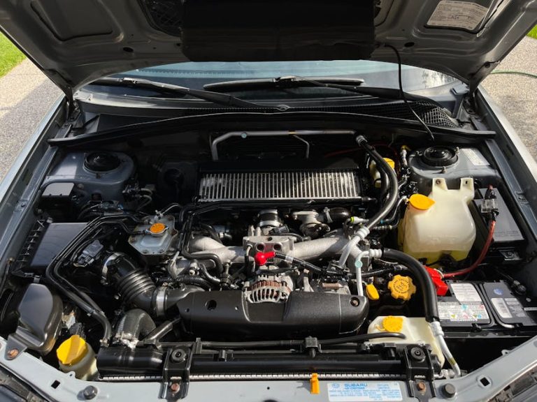
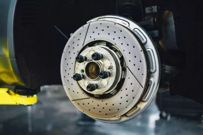
Common Causes of Overheating in Passenger Cars and Light Trucks