
The car brake bible - how brakes work, including disc brakes, drum brake, calipers, hoses, brake fluids and general brake maintenance, current and future brake technologies, DIY car maintenance and much more.
The Brake Bible
What do brakes do?
The simple answer: they slow you down.
The complex answer: brakes are designed to slow down a vehicle but probably not by the means that many people think. The common misconception is that brakes squeeze against a drum or disc, and the pressure of the squeezing action is what slows the car down. This in fact is only part of the equation. Brakes are essentially a mechanism to change energy types. When travelling at speed, a vehicle has kinetic energy. When the brakes are applied, the pads or shoes that press against the brake drum or rotor convert that energy into thermal energy via friction. The cooling of the brakes dissipates the heat and the vehicle slows down. It's the First Law of Thermodynamics, sometimes known as the law of conservation of energy. This states that energy cannot be created nor destroyed, it can only be converted from one form to another. In the case of brakes, it is converted from kinetic energy to thermal energy.
Angular force. Because of the configuration of the brake pads and rotor in a disc brake, the location of the point of contact where the friction is generated also provides a mechanical moment to resist the turning motion of the rotor.
Thermodynamics, brake fade and drilled rotors.
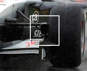
Picture credit: Formula1.com
Motorcycle riders and race car drivers are probably familiar with the term brake fade, used to describe what happens to brakes when they get too hot. A good example is coming down a mountain pass using the brakes rather than the engine and transmission to slow down. As you start to come down the pass, the brakes on heat up, slowing the car down. But if you keep using them, the rotors or drums stay hot and get no chance to cool off. At some point they can't absorb any more heat so the brake pads heat up instead. In every brake pad there is the friction material that is held together with some sort of resin and once this starts to get too hot, the resin starts to vapourise, forming a gas. Because the gas can't stay between the pad and the rotor, it forms a thin layer between the two whilst trying to escape. The pads lose contact with the rotor, reducing the amount of friction and voila. Complete brake fade.
The typical remedy for this would be to get the vehicle to a stop and wait for a few minutes. As the brake components cool down, their ability to absorb heat returns and the next time the brakes are applied, they seem to work just fine. This type of brake fade was more common in older vehicles. Newer vehicles tend to have less outgassing from the brake pad compounds but they still suffer brake fade. So why? It's still to do with the pads getting too hot. With newer brake pad compounds, the pads transfer heat into the calipers once the rotors are too hot, and the brake fluid starts to boil forming bubbles in it. Because air is compressible (brake fluid isn't) when the brake pedal is pressed, the air bubbles compress instead of the fluid transferring the motion to the brake calipers. Voila. Modern brake fade.
So how do the engineers design brakes to reduce or eliminate brake fade? For older vehicles, that vapourised gas is given somewhere to go. For newer vehicles, there are methods to cool the rotors off more effectively. Either way the result is cross-drilled or grooved brake rotors. While grooving the surface may reduce the specific heat capacity of the rotor, its effect is negligible in the grand scheme of things. However, under heavy braking once everything is hot and the resin is vapourising, the grooves give the gas somewhere to go, so the pad can continue to contact the rotor, allowing the car to stop.
The whole understanding of the conversion of energy is critical in understanding how and why brakes do what they do, and why they are designed the way they are. If you've ever watched Formula 1 racing, you'll see the front wheels have huge scoops inside the wheel pointing to the front (see the picture above). This is to duct air to the brake components to help them cool off because in F1 racing, the brakes are used viciously every few seconds and spend a lot of their time trying to stay hot. Without some form of cooling assistance, the brakes would be fine for the first few corners but then would fade and become near useless by half way around the track. In F1 in particular it actually becomes a balancing act because the brakes can't get too cool or they become ineffective (carbon-ceramic or carbon-carbon brakes need to be warm, not hot, to work properly), but they can't overheat because they suffer fade.
The following is a video showing Brembo doing brake tests on carbon-carbon F1 brakes:
Rotor technology.
If a brake rotor was a single cast chunk of steel, it would have terrible heat dissipation properties and leave nowhere for the vapourised gas to go. Because of this, brake rotors are typically modified with all manner of extra design features to help them cool down as quickly as possible as well as dissapate any gas from between the pads and rotors. The diagram here shows some examples of rotor types with the various modification that can be done to them to help them create more friction, disperse more heat more quickly, and ventilate gas. From left to right.
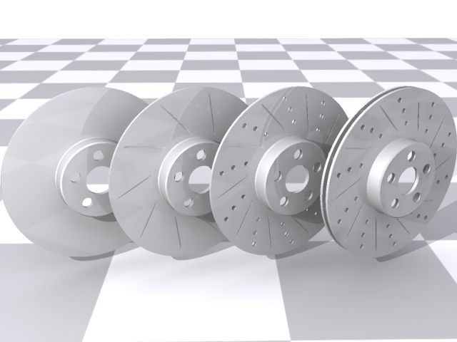
1: Basic brake rotor. 2: Grooved rotor - the grooves give more bite and thus more friction as they pass between the brake pads They also allow gas to vent from between the pads and the rotor. 3: Grooved, drilled rotor - the drilled holes again give more bite, but also allow air currents (eddies) to blow through the brake disc to assist cooling and ventilating gas. 4: Dual ventilated rotors - same as before but now with two rotors instead of one, and with vanes in between them to generate a vortex which will cool the rotors even further whilst trying to actually 'suck' any gas away from the pads.
An important note about drilled rotors: Drilled rotors are typically only found (and to be used on) race cars. The drilling weakens the rotors and typically results in microfractures to the rotor. On race cars this isn't a problem - the brakes are changed after each race or weekend. But on a road car, this can eventually lead to brake rotor failure - this would be A Bad Thing. This is worth menthioning only because of a lot of performance suppliers will supply drilled rotors for street cars without mentioning this little fact.
Certain cars require more upgrading for brakes than others. Mustangs happen to be one of those vehicles. AmericanMuscle does a great job explaining the Mustang braking system and how to go about upgrading from the stock form.
Big rotors.
How does all this apply to bigger brake rotors - a common sports car upgrade? Sports cars and race bikes typically have much bigger discs or rotors than the average family car or scooter. A bigger rotor has more material in it so it can absorb more heat. More material also means a larger surface area for the pads to generate friction with, and better heat dissipation. Larger rotors also put the point of contact with the pads further away from the axle of rotation. This provides a larger mechanical advantage to resist the turning of the rotor itself. To best illustrate how this works, imagine a spinning steel disc on an axle in front of you. If you clamped your thumbs either side of the disc close to the middle, your thumbs would heat up very quickly and you'd need to push pretty hard to generate the friction required to slow the disc down. Now imagine doing the same thing but clamping your thumbs together close to the outer rim of the disc. The disc will stop spinning much more quickly and your thumbs won't get as hot. That, in a nutshell explains the whole principle behind why bigger rotors = better stopping power.
Like the site? The page you're reading is free, but if you like what you see and feel you've learned something, a small donation to help pay down my car loan would be appreciated. Thank you.
The different types of brake.
All brakes work by friction. Friction causes heat which is part of the kinetic energy conversion process. How they create friction is down to the various designs.
Bicycle wheel brakes
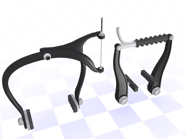
It's worth covering these because they're about the most basic type of functioning brake that exists, that can easily be observed while working, and be easily understand. The construction is very simple and out-in-the-open. A pair of rubber blocks are attached to a pair of calipers which are pivoted on the frame. When the brake cable is pulled, the pads are pressed against the side or inner edge of the bicycle wheel rim. The rubber creates friction, which creates heat, which is the transfer of kinetic energy that slows the bike down. There's only really two types of bicycle brake - those on which each brake shoe shares the same pivot point, and those with two pivot points. If you can look at a bicycle brake and not understand what's going on, the rest of this page is going to cause you a bit of a headache.
Drum brakes - single leading edge
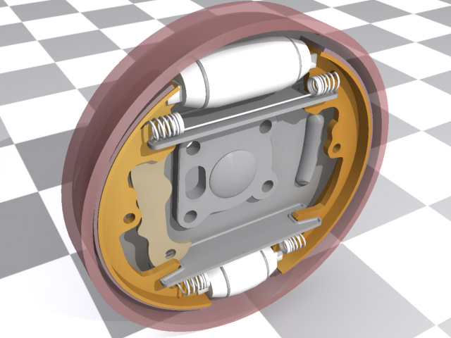
The next, more complicated type of brake is a drum brake. The concept here is simple. Two semicircular brake shoes sit inside a spinning drum which is attached to the wheel. When the brakes are applied, the shoes are expanded outwards to press against the inside of the drum. This creates friction, which creates heat, which transfers kinetic energy, which slows the car down. The example below shows a simple model. The actuator in this case is the blue elliptical object. As that is twisted, it forces against the brake shoes and in turn forces them to expand outwards. The return spring is what pulls the shoes back away from the surface of the brake drum when the brakes are released. See the later section for more information on actuator types.
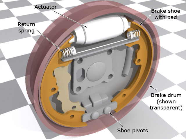
The "single leading edge" refers to the number of parts of the brake shoe which actually contact the spinning drum. Because the brake shoe pivots at one end, simple geometry means that the entire brake pad cannot contact the brake drum. The leading edge is the term given to the part of the brake pad which does contact the drum, and in the case of a single leading edge system, it's the part of the pad closest to the actuator. This diagram (right) shows what happens as the brakes are applied. The shoes are pressed outwards and the part of the brake pad which first contacts the drum is the leading edge. The action of the drum spinning actually helps to draw the brake pad outwards because of friction, which causes the brakes to "bite". The trailing edge of the brake shoe makes virtually no contact with the drum at all. This simple geometry explains why it's really difficult to stop a vehicle rolling backwards if it's equipped only with single leading edge drum brakes. As the drum spins backwards, the leading edge of the shoe becomes the trailing edge and thus doesn't bite.
Drum brakes - double leading edge
The drawbacks of the single leading edge style of drum brake can be eliminated by adding a second return spring and turning the pivot point into a second actuator. Now when the brakes are applied, the shoes are pressed outwards at two points. So each brake pad now has one leading and one trailing edge. Because there are two brake shoes, there are two brake pads, which means there are two leading edges. Hence the name double leading edge.
Disc brakes
Some background. Disc brakes were invented in 1902 and patented by Birmingham car maker Frederick William Lanchester. His original design had two discs which pressed against each other to generate friction and slow his car down. It wasn't until 1949 that disc brakes appeared on a production car though. The obscure American car builder Crosley made a vehicle called the Hotshot which used the more familiar brake rotor and calipers that we all know and love today. His original design was a bit crap though - the brakes lasted less than a year each. Finally in 1954 Citroën launched the way-ahead-of-its-time DS which had the first modern incarnation of disc brakes along with other nifty stuff like self-levelling suspension, semi-automatic gearbox, active headlights and composite body panels. (all things which were re-introduced as "new" by car makers in the 90's).
Disc brakes are an order of magnitude better at stopping vehicles than drum brakes, which is why they're found on the front of almost every car and motorbike built today. Sportier vehicles with higher speeds need better brakes to slow them down, so disc brakes are often used on the rear of those too.
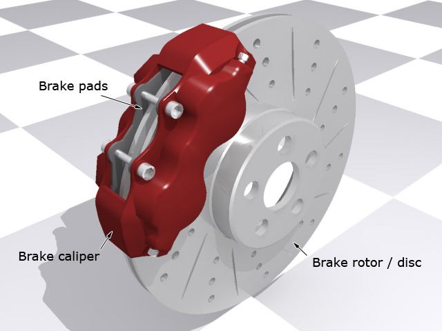
Disc brakes are again a two-part system. Instead of the drum, there is a disc or rotor, and instead of the brake shoes, there are brake caliper assemblies. The caliper assemblies contain one or more hydraulic pistons which push against the back of the brake pads, clamping them together around the spinning rotor. The harder they clamp together, the more friction is generated, which means more heat, which means more kinetic energy transfer, which slows the car down. Getting the idea now? Visit http://www.carid.com/brakes.html to find more brakes for your vehicle.
Standard disc brakes have one or two cylinders in them - also know as one or two-pot calipers. Where more force is required, three, or more cylinders can be used. Sports bikes have 4- or 6-pot calipers arranged in pairs. The disadvantage of disc brakes is that they are extremely intolerant of faulty workmanship or bad machining. If a regular car disc rotor is off by so much as 0.07mm (3/1000 inch) it will be Hell when the brakes are used. That ever-so-slight warp or misalignment is going to spin through the clamped calipers at some ungodly speed and the resulting vibration will make the driver wonder if they're driving down stairs. To combat this problem, which is particularly critical on motorbikes, floating rotors were invented.
The floating rotor.
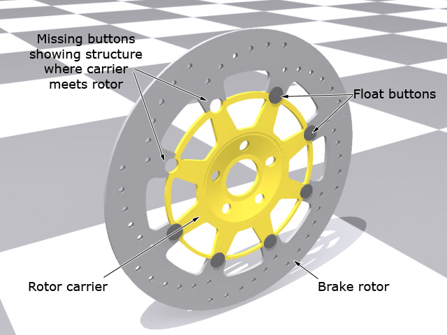
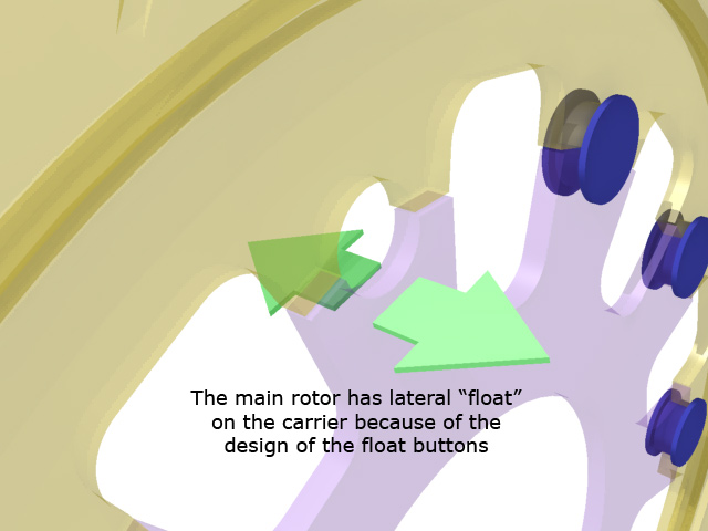
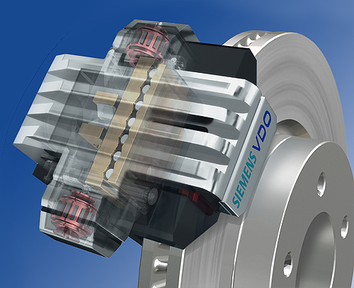
Standard brake rotors are cast in a single piece which bolts directly to the wheel or drive plate. If the mounting surface of the wheel or drive plate isn't perfectly flat, there will be vibration at speed. Floating rotors are typically cast in two pieces - the rotor and the carrier. The carrier is bolted to the wheel and the rotor is attached to the carrier using float buttons. The other method of floating a brake rotor is to have the rotor bolted directly to the wheel itself without a carrier, but the bolts have float buttons built into them.
These buttons allow the brake rotor some freedom to move laterally, but restrict the angular and rotational movement as if they were bolted directly to the wheel. This slight lateral motion (which can be less than 0.03mm) is just enough to prevent vibration in the brake system. As the calipers are mounted solidly, any warping or misalignment in the wheel or brake rotor mounting face can be compensated for because the rotor will "float" laterally on the float buttons. This side-to-side vibration is separated from the carrier by the float buttons themselves, so none of the resulting motion is transferred into the suspension or steering. Clever eh? The rendering to the right shows an extreme close-up of the brake disc shown above. The components are rendered slightly transparent to make it easier to see what's going on.
Radial calipers / radial brakes.
Around 2003, motorbikes started to hit the showrooms with a new feature - radial brakes. The magazines and testers will all say that radial brakes make the bike stop quicker. Not true - they have nothing to do with stopping power and everything to do with the design of the front forks of the bike. More and more bikes are coming out with upside-down forks. ie. instead of the fat canister part of the fork being at the bottom of the assembly, it's at the top. This means that the fork pistons are now the part of the suspension with the wheel attached to them. It also means that it's impossible to put a stiffening fork brace down there now because the brace would need to move with the wheel, and the length of the fork pistons precludes that.
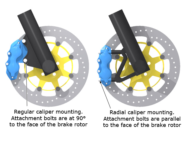
The stiffness of the front end is now entirely dependent on the size of the front axle. Bigger axle = stiffer front end. A side-effect of this design was that traditionally-mounted brake calipers could cause a lot of vibration in the steering because of flex between the wheel (with the brake disc bolted to it), and the fork leg (with the caliper). The slight tolerance allowed by floating brake rotors couldn't compensate for the amount of flexing in the forks. To reduce the brake-induced fork vibration, the brake calipers were moved around the rotors slightly so that they fell into the front-rear alignment of the wheel axle. There's less lateral flex at that point, which means less or no vibration. The caliper mounts were changed too. Traditional calipers bolt on to the forks with bolts going through them at 90° to the face of the brake rotor. With radial calipers, the bolts are aligned parallel to the brake rotor - effectively also in the front-rear alignment of the wheel. This design is a trickle-down technology from superbike racing where a radial caliper mount allows the racing teams to use different diameters of brake rotor by simply adding spacers between the caliper and the mounting bracket.
The image here shows the difference between traditional and radially mounted brake calipers.
Full-contact Disc brakes.
In the early 2000's there was a quiet but major revolution happening in the world of brakes, and it was being brought about by a Canadian company called NewTech. I say 'was' because whilst there is still reference to them spotted about the internet, their main site and contacts seem to have vanished. Anyway - rather than the piecemeal improvements that tend to happen in technology (slight design changes, slight materials improvements), the new system was a radical redesign from the ground up. NewTech designed a disc brake system called "full contact disc brakes". They looked at traditional pad and rotor design and figured that the pads only contact about 15% of the rotor surface at any one time. With a change of design, NewTech were able to add 5 more pads to the system so that 75% of the brake rotor is in contact with the pads at any one time.
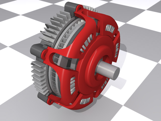
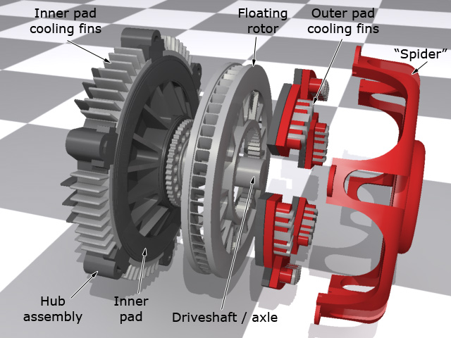
With traditional pads and rotors, the brake rotor is clamped between the pad. With the NewTech design, the brake rotor itself became a floating rotor, similar to those found on motorbikes. It was covered with a 'spider' (the red structure in my renderings) that had 6 brake pads on the inside of it. The hydraulic system acted on fully circular elastomer composite diaphragm behind the brake disc, mounted in the black structure in the renderings. This also had 6 pads on it which pushed the entire disc out against the 6 pads inside the spider. This provided an even force across the entire disc helping it to make even contact with all 12 pads.
To ensure the brakes remained cool, the system was covered in cooling fins connected to the outer pads to dissipate heat. The inner pads were fitted with a moulded thermal barrier made of a composite material. Special inserts made of a variety of frictional materials were distributed evenly on the entire surface of the pad. The range of materials was used to ensure performance under diverse conditions.
NewTech believed that the system had considerable advantages over conventional brakes with better cooling, higher strength and reduced noise and vibration.
NewTech sold truck and bus versions of these brakes into the haulage and public transport industry, but now Renault is considering introducing this system on its cars in conjunction with a new brake-by-wire system. Newtech's first OEM customer was to be Saleen who were going to put the system on their S7 supercar, but in the end went with conventional six-piston monoblock calipers instead. NewTech's website went offline in 2009 and has yet to be resurrected.
It's worth noting that this isn't actually the first time this has been tried in cars. Bugatti experimented with a system like this in the late 80's for inclusion on their 1991 EB110 supercar; it was going to be available as an option for the car. People who had experienced the brakes said they were just otherworldy, that the braking power was way beyond the capabilities of the average driver. They came from Aerospatiale, the French aerospace company, who also designed the chassis for the EB110 (this type of brake was being used in aircraft at the time). Bugatti dropped the idea because the brakes would have cost more than the rest of the EB110, which at $350,000 was by no means a cheap car.
The Siemens VDO Electric Wedge Brake.
Siemens VDO in Germany are trying to bring a prototype electric wedge brake (EWB) to the market. As much as it sounds like a high school prank involving underwear, it's actually the latest attempt to remove hydraulics from the braking circuit in a car. The EWB is an innovative idea based on technology developed by a company called eStop. Siemens acquired eStop early in 2005 and have been continuing their work on the wedge system ever since. The principle is both simple and clever. The brake pad is pressed against the brake rotor by means of a wedge-shaped thrust plate. The more the brake rotor turns, the harder the slope of the wedge forces the pads against it. Because of the shape of the wedge bearings and thrust plate and the rotation of the brake rotor, the pad is actually forced against the rotor harder the faster the rotor is spinning. In effect, a lot of braking force for very little input.
The system runs off a normal 12v vehicle electrical system which means no more hydraulics. It also allows the system to eliminate all the plumbing associated with ABS as the EWB is entirely electronically controlled. The final advantage, if it could be called that, is that it allows the first true all-electronic brake-by-wire system. Current brake-by-wire systems use electronics behind the brake pedal to send signals to actuators in the hydraulic system. With the EWB there is no hydraulic system so the only link from the brake pedal to the brake caliper is a 12v electrical feed and signal actuation wire.
The operation of the wedge system is based on several roller bearings and a wedge-shaped thrust plate connected to a pair of 12v electric motors. As the brake pedal is depressed, the signal is sent to the motors to start moving the thrust plate. Because of its shape and the design of the roller bearings, as the thrust plate moves, it forces the brake pad to press against the brake rotor. The reaction time of the electric motors can be measured in milliseconds - far quicker than any hydraulic system could react, so in theory, when connected to a full computer-monitored brake-by-wire system, the EWB ought to be able to shave milliseconds off brake reaction time. Doesn't sound like much but if it means a few less metres in stopping distance, that can only be a good thing.
The brake caliper unit itself has an intelligent wheel-braking module built into it. As well as the motors, bearings and wedges, the module also has a sensor system for monitoring movement and force - basically this is what replaces the traditional ABS items so each brake caliper becomes a self-governing ABS unit. Because there's no physical link back to the brake pedal any more, the ABS doesn't force the brake pedal to judder when it activates which will make it far more acceptable for a lot more drivers. Finally, because the system is totally electronic, the traditional cable-pulled handbrake can also be eliminated and replaced with a parking switch that simply activates all four EWB modules.
Of course there are pros and cons to any new system like this. Obviously reducing the weight and complexity of the braking system is a good thing, and because of the design of the EWB, there's a lot less space taken up in the engine bay, freeing up more room for the car designers to work with. But by removing the hydraulic lines, ABS actuators and sensors, and master and slave brake cylinders, the EWB concept becomes entirely reliant on the 12v electrical system and the vagaries of a computer. Knowing how often a single dodgy earth connections in a car can totally screw up the electrics, it's worth wondering what would happen if a grounding strap came loose and the electronic brake system started playing up. Will these brakes have a fail-safe or backup system like the double hydraulic circuits we use now, or will drivers sail off into some solid object because they have no brakes left? Siemens aren't clear on this matter.
Until we get the chance to render up some illustrations to better show how the system works, the ones here are from the Siemens press pack.
Picture credit: Siemens press kit
Brake pad compounds.
Just a quick word on brake pad compounds. Most pads used to use asbestos but we all know what that stuff is like. Today they use all manner of combinations of materials.
The pads themselves are made up of a friction material bonded to the backing plate. The brake caliper piston pushes against the backing plate and the friction material is pushed against the brake rotor. The material combinations typically fall into the following broad categories now.
- Organic
- These pads are well-suited for street driving because they wear well, are easy on the ears, don't chew up the rotors and don't spew dust everywhere. They're favoured for the average family saloon because they work well when they're cold. Of course the drawback is that they don't work so well when they get hot.
- Semi-metallic / sintered
- This is a good compromise between street and track. These seem to be the pad of choice for sportier vehicles such as the Subaru Impreza WRX. They won't work as well as organic pads when they are cold, so you need to be a bit wary of the first couple of stops. Conversely they do work well when hot. Occasionally the weak link in semi-metallic pads is the bonding material that holds the friction pad to the backing plate. There have been occasions where the friction material has come away completely. That's infrequent though.
- Metallic
- These pads are typically reserved for racing or the extremely rich. They squeal and dust like crazy, are hard on rotors and don't work well when cold.
- Ceramic
- Ceramic pads still have metal fibres (about 15% vs. about 40% for semi-metallic) but they are copper instead of steel and therefore cause less wear and transfer heat better. They don't fade as easily as other pads, cool faster, last longer, and are effectively silent, as the sound they genereate is outside of the human range of hearing. Dogs will go crazy though. The dust created by ceramic pads is also very light in color so your wheels look cleaner.
Brake squeal.
Squealing brakes are a sign of one of two things : the friction material is all gone and the backing plate is being jammed against the brake rotor, or the fit of the brake pad against the caliper piston isn't as snug as it could be. Either way, the squealing is the result of an extremely high-frequency vibration between the pad, the caliper piston and the brake rotor. Some vehicles have problems with squealy brakes right from the factory. In those cases, simply changing brake pad manufacturer can often cure the problem as the different pads will have a slightly different harmonic frequency, which is harder to attain. A classic example was one of the BMW R1100 touring bikes. From the factory, they'd squeal like crazy, and BMW redesigned the brake calipers and rotors a couple of times until they finally just switched to a different brand of pads and the problem vanished.
Solving brake squeal.
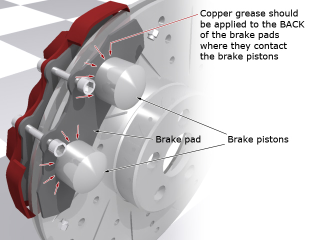
For a reasonably competent home mechanic, a good way to solve brake squeal is to put some copper-based grease on the back of the brake pads. That's very important so I'll say it again in CAPS : THE BACK. Copper grease is extremely resistant to pressure and heat and if any gets on the front of the pads, you'll need new pads and rotors or discs. (The picture here shows a cutaway of a disc brake assembly. The red caliper housing on the right is missing to show the two silver brake pistons.) The idea is that the copper grease creates a small pocket of sticky lubrication between the front side of the brake pistons and the back side of the brake pads. This is usually enough to prevent the high-frequency squeal. If you're not happy doing this yourself (working on a safety-critical part of a car like the brakes isn't something just everybody should be doing) then find a friendly greasemonkey to do the work instead.
There's a few products on the market that I've heard of and/or used in the past. Noisefree is one of them CRC Disc Brake Quiet is another and then there's Copaslip. I (the author) have used Copaslip on my vehicles before with no problems. I've had positive reviews of the CRC product from people using it motorbikes and cars. Noisefree is a new player so if you've used their product and have any comments, drop me a line. All three are available in America, but I think if you're in Europe you're limited to Copaslip. Or the internet of course.
Copper grease and rubber
Whilst copper grease such as Copaslip works well in the short term to solve brake squeal, long-term, it has an adverse affect on the rubber dust seals of the caliper pistons. This can lead to the seal deteriorating or failing completely. If that happens, it leaves the piston and it's surface exposed to the very elements from which it should be protected. Just so you know.
The other solution to brake squeal
Whilst the ultra high frequency vibration is one cause of brake squeal, the other biggie is related to suspension alignment. Driving on badly-maintained roads, mountaineering through pot-holes or kerbing wheels all make the suspension move around in ways it was never really designed to cope with, and this in turn leads to the suspension bushes becoming stressed. Normally, re-aligning the wheels on a vehicle is corrected by mechanical adjustment only. If the mounting rubbers are not de-stressed first, then it leads to the transfer of the sound generated during braking into the chassis and body which then amplifies it to where we can hear it. Sort of like a giant record player with the suspension as the pickup needle and the entire car as the speaker. If copper grease doesn't solve a squealing brakes problem, look into a proper suspension realignment and possibly new suspension bushes.
The eBay problem
This paragraph may seem a little out of place but I have had a lot of problems with a couple of eBay members (megamanuals and lowhondaprelude) stealing my work, turning it into PDF files and selling it on eBay. Generally, idiots like this do a copy/paste job so they won't notice this paragraph here. If you're reading this and you bought this page anywhere other than from my website at car-bibles.com, then you have a pirated, copyright-infringing copy. Please send me an email as I am building a case file against the people doing this. Go to car-bibles.com to see the full site and find my contact details. And now, back to the meat of the subject....
Brake actuators.
Brakes are all well and good, but there needs to be some method of applying them in order for them to work. The method by which the force from a hand or foot reaches the brake itself is all to do with the brake actuator system.
Cable-operated
This is about as basic as it gets. A cable is connected to a lever at each end. Press on one lever with a foot or squeeze it with a hand, and it pulls the lever at the other end. On the back of the brake-end lever there's an elliptical cam which rotates inside a circular cup in the brake shoe. As the long axis of the ellipse rotates, it forces the brake shoes to move apart. In the case of a bicycle brake, the brake-end of the cable just pulls the two calipers together.
Solid bar connection
One step up, and found on the rear brake of older motorbikes, the solid bar connection. This allows the use of mechanical advantage (see below) to amplify the force on the pedal or lever before it gets to the brakes themselves. Typically these systems are used on drum brakes with the elliptical actuator described above. The disadvantage of this system is that it needs hinge and pivot points that match the position of the suspension components. If they're not present, going over a bump could put the brakes on as the suspension moves relative to the lever.
Single-circuit hydraulic
Another step up and we get to the type of brake system used on most cars and motorbikes today. Gone are the cables and bars, replaced instead with a system of plungers, reservoirs and hydraulic fluid. Single-circuit hydraulic systems have three basic components - the master cylinder, the slave cylinder and the reservoir. They're joined together with hydraulic hose and filled with a non-compressible hydraulic fluid (see brake fluid below). When the brake pedal is pressed, or the brake lever is squeezed, a small piston assembly is moved inside the master cylinder. Because the brake fluid does not compress, that pressure is instantaneously transferred through the hydraulic brake line to the slave cylinder where it acts on another piston assembly, pushing it out. That slave assembly is either connected to a lever to activate the brakes, or more commonly, is the brake caliper itself, with the slave cylinder being the piston that acts directly on the brake pads. Because of the arrangement of the slave cylinder, heat from the brakes can be transferred back into the brake fluid.
Dual-circuit hydraulic
Dual-circuit hydraulic systems are available on high-end luxury vehicles and newer motorbikes, in particular BMW bikes. These have two separate circuits. One is the command circuit - that's the one acted on with the brake pedal or lever. The second is a separate circuit controlled by an onboard computer, and that's the one which is actually connected to the brakes. As the brakes are applied, a pressure signal is sent via the command circuit to the brake computer. It measures the amount of force being applied, and using a servo / pump system, applies the same force to the secondary circuit to activate the brakes. If something out of the ordinary happens, like the driver trying to slam on the brakes at 100mph, the computer will realise that this would result in a skid or spin, and will not send the full pressure down the secondary circuit, instead deciding to use the speed and ABS sensors to determine the optimal brake pressure to maintain control of the vehicle. The advantage of a dual-circuit system is that the command circuit never gets heat transferred into it because it is totally separated from the brakes themselves. The disadvantage of course is that there are now two hydraulic circuits to maintain.
Brake-by-wire
The most advanced system of brakes to date are brake-by-wire. These are a direct copy of some styles of racing brakes and are very similar to the dual-circuit hydraulic system described above, but instead of the command circuit being hydraulic, it's replaced with electronics. The brake pedal or lever is connected to a hypersensitive rheostat (measures electrical resistance). The further it is pushed, the greater the electrical signal sent to the brake computer. From there on, it performs just like the secondary circuit described above. The advantage to this system is that the brake pedal or lever can be placed just about anywhere as it is no longer encumbered by the plumbing that goes with a hydraulic circuit. To combat driver complaints of "lack of feel" in the brakes, most brake-by-wire systems have a reverse feedback loop built in. This measures the pressure being applied to the brakes on the secondary circuit, and actuates an electrical resistor in the pedal or lever assembly to provide resistance. This is needed because there is no physical connection to any part of the brake system at all.
Like the site? The page you're reading is free, but if you like what you see and feel you've learned something, a small donation to help pay down my car loan would be appreciated. Thank you.
Mechanical advantage
(or why you can stop a 2-ton car with one foot).
If you did any sort of physics classes when you were back in school, you might remember something called mechanical advantage. In its most basic form, mechanical advantage is the ratio of force-in to force-out in a mechanical system. Mechanical Advantage = Effort Torque/Load Torque.
For example a 20kg weight 1 metre from a pivot can lift a 40kg weight 0.5m from the pivot on the other side. The effort torque and load torque calculations are to do with force in Newtons and distance from pivot point. Hence torque is measured in Newton-metres, or Nm. A Newton is the amount of force required to accelerate a mass of one kilogram by one metre per second². On Earth, where acceleration due to gravity is 9.8m/s², the force exerted upon a mass of 1kg is 9.8N (usually rounded up to 10N). Another popular notation is lbf.ft - pound-force-feet, commonly referred to as foot-pounds. 1 Newton-metre is equivalent to 0.737 foot-pounds.
The diagram below shows a simple lever system on a pivot. The load torque is 200Nm, and the effort torque is also 200Nm. Mechanical advantage = effort / load, which in this case is 200 / 200, which is 1. ie. the system is balanced.
Now imagine increasing the weight on the effort side to 30kg instead of 20kg, but leaving everything else the same. The load torque is still 200Nm, but the effort torque is now 300Nm. Mechanical advantage = effort / load, which is 300 / 200, which is 1.5. Any mechanical advantage value larger than 1.0 means that the effort has the advantage. In this case, a 30kg weight which is lighter than the 40kg load, is able to lift it off the ground.

If you now take your new-found / remembered knowledge about physics and look at the simple lever brake system, you'll realise how it's possible to generate enough force using a foot to stop a car or motorbike. Look at this diagram of the lever-operated cam brake.
This system has 4 levers in it. The middle two have no mechanical advantage as the levers are connected the same distance from the pivot in each case. However, look at the pedal. The values I've put in are arbitrary but they serve the purpose. On the pedal we have some amount of force 20cm from the pivot, but the other end of the lever is only 5cm from the pivot. This gives us a mechanical advantage of 4 on the brake lever (20cm / 5cm).
At the other end, the lever attached to the cam is still a lever system - it's just bent. The input lever is 10cm long but the cam is only 4cm across - or 2cm to the tip from the pivot. So at the brake cam we have a mechanical advantage of 5. (10cm / 2cm). So across this entire system, we have a total mechanical advantage of 20 - 4 from the brake pedal and 5 from the lever and cam. Apply force to this little system and be amazed. The units of force used are irrelevant - they're multiplied just the same. To use easier-to-comprehend values, let's imagine that when you're braking, your foot is pushing on the brake pedal with about 60pounds of force - 27Kg. Through the brake pedal, that is amplified 4 times to 240pounds, and through the lever and cam its amplified a further 5 times from 240pounds to 1200pounds. You pushed the pedal with 60pounds of force, but the cam inside the drum brake is being forced out against the brake drum with 1200pounds of force - about 544Kg. Sweet.
Mechanical advantage as applied to hydraulics.
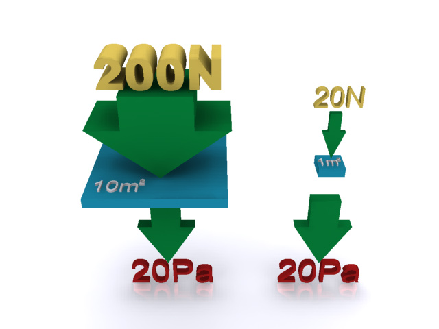
Most braking systems now use hydraulics. This is a slight change in the equation but the concept of mechanical advantage still exists, this time by the use of pressure equations. Pressure = force / area. If 20 Newtons of pressure is applied to 1m², it's the same as applying 200 Newtons to 10m². Why? Because 20 Newtons of force divided by 1m² of area generates 20 Pascals of pressure. Similarly, 200N / 10m² is also 20Pa.
Thinking of that in terms of a hydraulic braking system, it becomes clear how mechanical advantage works. Brake fluid is incompressible - it has to be. This is good because it makes calculation for hydraulic brake systems quite easy - internal pressure can be eliminated from the equation.
Split the system into two parts - input and output - the brake pedal and the brake caliper piston.
For each part, Pressure = Force / Area. The Pressure is the same at all points in the system, so some basic algebra gives a simple formula:
Using our previous example, we apply 60pounds (27Kg) of input force to the brake pedal. This is attached to a master piston which (for example) is 1.25cm across - ie. it has a surface area of 0.000491m² (remember your maths? area = PI x r²). At the other end of the system is the caliper piston, which for example is 2cm across - ie. it has a surface area of 0.001257m². Using our sparkly new formula, the output force from the caliper piston is
60 x (0.001257m² / 0.000491m²) Get your calculator out and that comes out to 154pounds (69.8Kg) - more than double the force at the brake pedal. The ratio of output area to input area is sometimes referred to as the area differential.
So that, my friend, is why a speeding vehicle can be stopped with a single foot.